α2 Simple Application Controller. Manual in 6 languages (2018) - 1
ENG
GER
FRE
ITL
ESP
SWE
α2 Simple Application Controller
HARDWARE MANUAL
RUS
HARDWARE-HANDBUCH
MANUEL DU MATÉRIEL
MANUALE HARDWARE
MANUAL DE HARDWARE
MASKINVARUHANDBOK
РУКОВОДСТВО ПО АППАРАТНОЙ ЧАСТИ
α2 Simple Application Controller
ENG
Hardware Manual
Manual number: JY992D97301
Manual revision: N
Date:
4/2018
ENG-i
Guidelines for the Safety of the User and Protection of equipment
This manual provides information for the use of the α2 Series Controllers. The manual has
been written to be used by trained and competent personnel. The definition of such a person
or persons is as follows;
a) Any engineer who is responsible for the planning, design and construction of automatic
equipment using the product associated with this manual should be of a competent
nature, trained and qualified to the local and national standards required to fulfill that
ENG
role. These engineers should be fully aware of all aspects of safety with regards to
automated equipment.
b) Any commissioning or service engineer must be of a competent nature, trained and
qualified to the local and national standards required to fulfill that job. These engineers
should also be trained in the use and maintenance of the completed product. This
includes being completely familiar with all associated documentation for the said
product. All maintenance should be carried out in accordance with established safety
practices.
c) All operators of the completed equipment (See Note) should be trained to use that
product in a safe manner in compliance to established safety practices. The operators
should also be familiar with documentation which is connected with the actual operation
of the completed equipment.
Note : The term ‘completed equipment’ refers to a third party constructed device which
contains or uses the product associated with this manual.
For cleaning, perform dry wiping without using chemicals.
Notes on the Symbols Used in this Manual
At various times through out this manual certain symbols will be used to highlight points of
information which are intended to ensure the users personal safety and protect the integrity of
equipment. Whenever any of the following symbols are encountered its associated note must
be read and understood. Each of the symbols used will now be listed with a brief description of
its meaning.
Hardware Warnings
1) Indicates that the identified danger WILL cause physical and property damage.
2) Indicates that the identified danger could POSSIBLY cause physical and property
damage.
3) Indicates a point of further interest or further explanation.
Software Warnings
4) Indicates special care must be taken when using this element of software.
5) Indicates a special point which the user of the associate software element should
be aware of.
6) Indicates a point of interest or further explanation.
ENG-iii
• Under no circumstances will Mitsubishi Electric be liable or responsible for any
consequential damage that may arise as a result of the installation or use of this equipment.
• All examples and diagrams shown in this manual are intended only as an aid to
understanding the text, not to guarantee operation. Mitsubishi Electric will accept no
responsibility for actual use of the product based on these illustrative examples.
• Please contact a Mitsubishi Electric distributor for more information concerning applications
in life criticalo situations or high reliability.
Further Information Manual Lists
Manual Name
Manual No.
Description
This manual contains hardware explanations for
α2 Hardware Manual
~
JY992D97301
wiring, installation and specification for the α2
(This manual)
Series controllers.
α2 Programming Manual
This manual contains instruction explanations for
~
JY992D97101
<English only>
the α2 Series controllers.
α Software Manual
This manual contains explanations of operation
{
JY992D74001
<English only>
of AL-PCS/WIN-E Programming Software.
α2 Series Communication
This manual contains explanations for the setup,
{
JY992D97701
messaging, diagnostics, bit assignments, etc for
User’s Manual
<English only>
communications using the α2 series controller.
This manual contains installation explanations
α2 Series Installation Manual
JY992D97501
for the α2 Series controller.
AL2-4EX, AL2-4EX-A2,
This manual contains installation explanations
AL2-4EYR, AL2-4EYT
JY992D97401
for the AL2-4EX, AL2-4EX-A2, AL2-4EYR and
Installation Manual
AL2-4EYT extension module.
AL2-EEPROM-2
This manual contains hardware explanations for
JY992D96801
Hardware Manual
the AL2-EEPROM-2.
AL2-2DA
This manual contains installation explanations
JY997D09301
Installation Manual
for the AL2-2DA.
AL2-2PT-ADP
This manual contains installation explanations
JY997D09401
Installation Manual
for the AL2-2PT-ADP.
AL2-2TC-ADP
This manual contains installation explanations
JY997D09501
Installation Manual
for the AL2-2TC-ADP.
AL-232CAB
This manual contains hardware explanations for
JY992D76001
Hardware Manual
the AL-232CAB.
AL2-GSM-CAB
This manual contains hardware explanations for
JY992D97201
Hardware Manual
the AL2-GSM-CAB.
This manual contains hardware explanations of
AL-ASI-BD, AL2-ASI-BD
JY992D81401
wiring, installation and specification, etc. for AL-
Hardware Manual
ASI-BD and AL2-ASI-BD.
~ Refer to these manuals.
{ Refer to this manual if necessary.
Refer to the content of these manuals if necessary though it is included in α2 Hardware
Manual.
ENG-iv
Abbreviations
The following definitions or abbreviations will be used throughout this manual.
• The AL-PCS/WIN-E software will be referred to as the VLS software or the programming
software.
• The α2 Series Simple Application Controller may be referred to as the α2 series, the α2
series controller or the main module.
ENG
• Function Blocks may be referred to as FB(s).
• Function Block Diagram may be referred to as FBD.
• Input/Output may be referred to as I/O.
• Personal Computer may be referred to as PC
• Microsoft Windows®, Windows®
95, Windows®
98, Windows® Me, WindowsNT®
Workstation 4.0, Windows® 2000, Windows® XP and Windows Vista® may be referred to
generically as Windows.
Registration
• Microsoft Windows®, Windows®
95, Windows® 98, Windows® Me, WindowsNT®
Workstation 4.0, Windows® 2000, Windows® XP and Windows Vista® are either
registered trademarks or trademarks of Microsoft Corporation in the United States and/or
other countries.
• The company name and the product name to be described in this manual are the
registered trademarks or trademarks of each company.
ENG-v
Table of Contents
Guidelines of Safety
ENG-iii
1. Introduction
ENG-1
1.1
Special Features of the α2 Series System
ENG-2
ENG
1.2
Available Models
ENG-3
1.3
Dimensions and Each Part Name
ENG-4
1.4
System Configuration
ENG-6
1.5
Version Up List
ENG-7
1.6
Applicable Programming Software
ENG-7
2. Specifications
ENG-8
2.1
Power Supply Specification
ENG-8
2.2
Input Specification
ENG-9
2.3
Output Specification
ENG-11
2.4
General Specification
ENG-12
3. Installation
ENG-14
3.1
Installation Mounting Notes
ENG-14
3.2
DIN RAIL Mounting of Main Unit
ENG-15
3.2.1
Installation
ENG-15
3.2.2
Remove
ENG-15
3.3
Direct Mounting of Main Unit
ENG-16
3.4
Install Extension Module(AL2-14MR-*,AL2-24MR-*)
ENG-17
4. Wiring
ENG-18
4.1
Installation Wiring Notes
ENG-18
4.2
Wire Size
ENG-19
4.3
Power Supply
ENG-20
4.4
AC Power Supply and Input Wiring
ENG-21
4.4.1
AC Power Supply and Input Wiring
ENG-21
4.4.2
AL2-4EX-A2 Input Wiring
ENG-21
4.5
DC Power Supply and Input Wiring
ENG-22
4.5.1
DC Power Supply and Source (“+” Common) Input Wiring Diagram
ENG-22
4.5.2
AL2-4EX Source (“+” Common) Input Wiring Diagram
ENG-22
4.5.3
DC Power Supply and Sink (“-” Common) Input Wiring Diagram
ENG-23
4.5.4
AL2-4EX Sink (“-” Common) Input Wiring Diagram
ENG-23
4.6
Output Relay and Transistor Wiring
ENG-24
4.6.1
Relay Output Wiring Diagram main unit (AC and/or DC)
ENG-24
4.6.2
Relay Output Wiring Diagram AL2-4EYR (AC and/or DC)
ENG-25
4.6.3
Transistor Output (Source or “+” Common Only) Wiring Diagram AL2-4EYT... ENG-26
5. Terminal Layout
ENG-27
6. AL2-EEPROM-2
ENG-30
6.1
Installation
ENG-31
ENG-vii
7. AL-232CAB
ENG-32
7.1
Introduction
ENG-32
7.1.1
External Dimensions
ENG-32
7.2
Connected to AL-232CAB cable
ENG-33
8. AL2-GSM-CAB
ENG-36
8.1
Introduction
ENG-36
8.1.1
External Dimensions
ENG-36
8.1.2
System Configuration with using AL2-GSM-CAB
ENG-37
8.2
Installation
ENG-38
8.3
Remote Maintenace with a Modem
ENG-40
8.3.1
Recommended Modems
ENG-40
8.3.2
RS-232C Straight Cable Between Modem and AL2-GSM-CAB
ENG-40
8.3.3
Modem Setting
ENG-41
9. AL2-ASI-BD (AL2-14MR-*, AL2-24MR-* )
ENG-44
9.1
Introduction
ENG-44
9.1.1
External Dimensions
ENG-44
9.1.2
System Configuration
ENG-45
9.2
Specifications
ENG-45
9.3
Wiring & Installation
ENG-46
9.3.1
Installation
ENG-46
9.3.2
Wiring
ENG-47
9.4
Slave Address Setting & Diagnostics
ENG-47
9.4.1
Setting Slave Address
ENG-47
9.4.2
Applicable Error checks
ENG-47
10.DCF77 Radio Clock
ENG-48
10.1 Introduction
ENG-48
10.2 System Configuration
ENG-49
10.3 Specifications
ENG-49
10.4 Wiring
ENG-50
10.4.1 Wiring
ENG-50
10.4.2 DCF77 Setup from α2 display
ENG-51
10.4.3 Automatically Start
ENG-52
10.4.4 Automatically Stop
ENG-52
10.4.5 Verification of Received Time
ENG-52
11.AL2-2DA (AL2-14MR-*, AL2-24MR-*)
ENG-54
11.1 Introduction
ENG-55
11.1.1 External Dimensions
ENG-55
11.1.2 System Configuration
ENG-55
11.2 Specification
ENG-56
11.3 Wiring & Installation
ENG-57
11.3.1 Installation
ENG-57
11.3.2 Wiring
ENG-58
11.3.3 Applicable Error checks
ENG-59
ENG-viii
12.AL2-2PT-ADP
ENG-60
12.1 Introduction
ENG-61
12.1.1 External Dimensions
ENG-61
12.2 System Configuration
ENG-61
12.3 Specification
ENG-62
12.4 Wiring and Installation
ENG-64
12.4.1 Installation
ENG-64
12.4.2 Wiring
ENG-65
ENG
12.4.3 Choosing a Temperature Scale
ENG-66
12.4.4 Offset Adjustment
ENG-67
12.4.5 Gain Adjustment
ENG-68
12.4.6 Fine Offset Adjust
ENG-70
12.4.7 Applicable Error checks
ENG-71
13.AL2-2TC-ADP
ENG-72
13.1 Introduction
ENG-73
13.1.1 External Dimensions
ENG-73
13.2 System Configuration
ENG-73
13.3 Specification
ENG-74
13.4 Wiring and Installation
ENG-76
13.4.1 Installation
ENG-76
13.4.2 Wiring
ENG-77
13.4.3 Choosing a Temperature Scale
ENG-78
13.4.4 Offset Adjustment
ENG-79
13.4.5 Gain Adjustment
ENG-80
13.4.6 Fine Offset Adjust
ENG-82
13.4.7 Applicable Error Checks
ENG-83
14.Key, System Bit and Function Block Lists
ENG-84
14.1 Key Lists
ENG-84
14.2 System Bit Lists
ENG-85
14.2.1 System Bit Lists
ENG-85
14.2.2 Control Bit Lists
ENG-86
14.3 Function Block Lists
ENG-87
15.Diagnostics
ENG-91
15.1 Input Status Error
ENG-92
15.2 Output Status Error
ENG-92
15.3 TOP MENU is not Displayed
ENG-93
15.4 Cannot enter Run Mode
ENG-94
15.5 Incorrect Clock Data
ENG-94
15.6 The “?” appears on the Display
ENG-94
15.7 Cannot Use an Operation Key
ENG-95
15.8 Incorrect LCD display
ENG-96
15.9 Memory Cassette Is Not Working Correctly
ENG-96
15.10Cannot Communicate with the AS-interface Master Module
ENG-97
15.11Cannot Communicate with AL-PCS/WIN-E
ENG-98
ENG-ix
Introduction 1
1.
Introduction
The α2 series can be easily used in all places where control is needed for the home, office, or
factory. The controller outputs cycle ON/OFF to control electrical equipment per the Function
Block program.
The explanation of the instructions and the operation of main unit can be found in α2
Programming Manual. An explanation of the AL-PCS/WIN-E programming software can be
ENG
found in the α Series Software Manual.
Applications
The α2 series is designed to be used in automatic applications including those listed below.
- Automation of lights, air-conditioning, or watering systems
- The opening and shutting of gates
- Easy security systems
- Domestic animal and pet food distribution systems
- Control of stockyards and greenhouses
However, the α2 series is not designed to be used in the following applications. Please contact
your local Mitsubishi Electric representative for more information.
- Applications where high reliabilities such as nuclear power control, railway facilities,
airline facilities, vehicles, combustion equipment, and medical equipment are required.
- Applications in life critical situations.
ENG-1
Introduction 1
1.1
Special Features of the α2 Series System
1) Display message and Function Block data
The α2 series can display the state of operation and the alarm on the LCD display as a
message. It can display the following contents by using the display function block. The
value of displayed timers and counters can be changed in the RUN mode.
- Total characters on LCD display: 12 characters × 4 lines
- Display Items: Message, value (current or set) of timer and counter, analog values, etc
2) The programming in the personal computer is fast and easy
The programming software AL-PCS/WIN-E for Windows can create and save programs.
The programming can be done using a pictorial method in which lines are used to connect
function blocks on a programming screen.
Direct programming using the α2 controller front panel keys is also available.
3) LCD image send via GSM modem
The α2 (AL2-14MR-*,AL2-24MR-*) series is able to send the LCD image as an E-mail
using a GSM modem. The user can monitor application status by accessing the diagnostic
message sent as an E-mail via GSM modem
4) Supports computer link using dedicated protocol
The α2 (AL2-14MR-*,AL2-24MR-*)series supports computer link (dedicated protocol).
User-specific application software using computer link can change schedule data,
parameters within Function Blocks and provide condition monitoring of the application.
5) Enhancement of clock function
The weekly timer and the calendar timer function have many switches that can be set and
provide powerful time dependant control capabilities.
6) Analog input, 0 - 10V/0 - 500, -50°C - 200°C (PT100), -50°C - 450°C (K-type thermocouple):
The DC input for the α2 series can accept of 0 - 10V signals with a resolution of 0 - 500.
7) Analog output, 0 - 4000/0 - 10V, 0 - 2000/4 - 20mA:
The α2 series can output voltage and current signals.
8) High speed counter, Max. 1kHz
The α2 series has high speed counters (Max. 2 points) when using AL2-4EX (EI1, EI2).
9) High current output capability
Table 1.1: High Current Output Capability
Output Type
Capability
AL2-10MR-*: O01 - O04
AL2-14MR-*: O01 - O06
8A/Common
Relay
AL2-24MR-*: O01 - O04
AL2-24MR-*: O05 - O09
2A/Point (4A/Common)
AL2-4EYR: EO1 - EO4
Transistor
AL2-4EYT: EO1 - EO4
1A/Point
10)Built-in EEPROM
The built in EEPROM eliminates the need for battery backed data.
11)Supports 7 languages:
The α2 series supports 7 languages (English, German, French, Italian, Spanish, Swedish,
and Russian*1). The displayed language can be selected in the TOP MENU.
*1 V3.00 or later
ENG-2
Introduction 1
1.2
Available Models
Table 1.2:Main Units
Input
Output
MASS
Power
Dimensions
Model
(Weight)
Supply
Type
Number
Type
Number
mm (inches)
kg (lbs)
100 - 240V
100 - 240V
71.2 x 90 x 52
0.21
AL2-10MR-A
6
RELAY
4
AC~
AC~
(0.47)
ENG
24V DC
(2.8 x 3.54
0.20
AL2-10MR-D
24V DC
6
RELAY
4
Sink/Source
x 2.05)
(0.44)
100 - 240V
100 - 240V
AL2-14MR-A
8
RELAY
6
AC~
AC~
0.30*1
24V DC
(0.66)
124.6 x 90 x 52
AL2-14MR-D
24V DC
8
RELAY
6
Sink/Source
100 - 240V
100 - 240V
(4.91 x 3.54
0.35*1
AL2-24MR-A
15
RELAY
9
AC~
AC~
x 2.05)
(0.77)
24V DC
0.30*1
AL2-24MR-D
24V DC
15
RELAY
9
Sink/Source
(0.66)
*1 Without extension modules.
Table 1.3:Extension Modules/Adapters
Input
Output
MASS
Model
(Weight)
Type
Number
Type
Number
kg (lbs)
AL2-4EX-A2
220 - 240V AC~
4
⎯
24V DC, Sink/
AL2-4EX
4
⎯
Source
AL2-4EYR
⎯
RELAY
4
0.05
AL2-4EYT
⎯
TRANSISTOR
4
(0.11)
AL2-ASI-BD
AS-interface Input
4
AS-interface Output
4
Analog
AL2-2DA*1
⎯
2
(“0 to 10V” or “4 to 20mA”)
AL2-2PT-ADP*1
PT100 Sensor
2
Analog (0 to 10V)
2
Thermocouple
AL2-2TC-ADP*1
2
Analog (0 to 10V)
2
Sensor (K Type)
0
*1 When using AL2-2DA, AL2-2PT-ADP or AL2-2TC-ADP, α2 main module must be V2.00
or later.
ENG-3
Introduction 1
1.3
Dimensions and Each Part Name
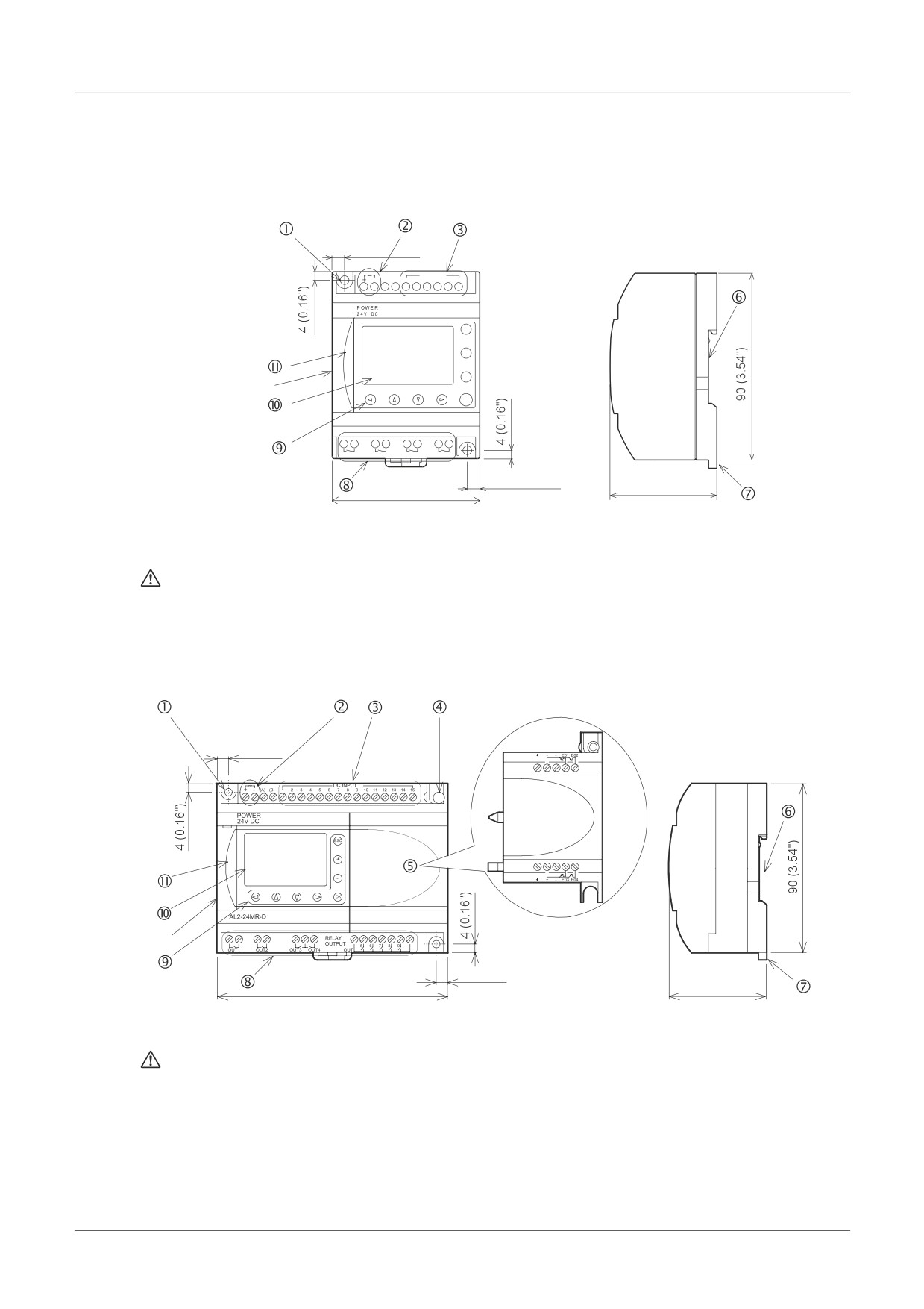
Figure 1.1: Each Part Name(AL2-10MR-*)
6 (0.24")
DC INPUT
-
(A) (B)
1
2
3
4
5
6
ESC
+
-
Nameplate
OK
AL2-10MR-D
RELAY OUTPUT
OUT1
OUT2
OUT3
OUT4
6 (0.24")
71.2 (2.8")
52 (2.05")
Nameplate printing
is a mark that instructs to use the cable with an appropriate temperature rating
(80°C or more) for wiring.
Figure 1.2: Each Part Name(AL2-14MR-*,AL2-24MR-*)
6 (0.24")
Nameplate
6 (0.24")
124.6 (4.91")
52 (2.05")
Nameplate printing
is a mark that instructs to use the cable with an appropriate temperature rating
(80°C or more) for wiring.
ENG-4
Introduction 1
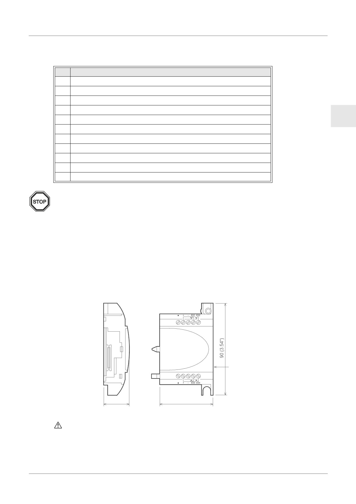
Table 1.4: Each Part Name
Ref.
Item Description
1
Mounting hole, φ4.2 mm
2
Power terminals
3
Input terminals
4
Mounting screw for the extension cover or extension module
ENG
5
Extension cover or extension module(AL2-14MR-*,AL2-24MR-*)
6
Groove for DIN rail mounting (Width of DIN rail 35mm <DIN EN 50022>)
7
DIN-RAIL mounting clips
8
Output terminals
9
Operation keys
10
Liquid crystal display
11
Programming port cover
Note;
• Refer to chapter 7 about dimensions of the AL-232CAB
• Refer to chapter 8 about dimensions of the AL2-GSM-CAB.
• Refer to chapter 9 about dimensions of the AL2-ASI-BD.
• Refer to chapter 11 about dimensions of the AL2-2DA.
• Refer to chapter 12 about dimensions of the AL2-2PT-ADP.
• Refer to chapter 13 about dimensions of the AL2-2TC-ADP.
Figure 1.3: Dimensions (AL2-4EX, AL2-2EX-A2, AL2-4EYR, AL2-4EYT)
Unit: mm (inches)
Nameplate
24.5 (0.96")
53.1 (2.09")
Nameplate printing
is a mark that instructs to use the cable with an appropriate temperature rating
(80°C or more) for wiring.
ENG-5
Introduction 1
1.4
System Configuration
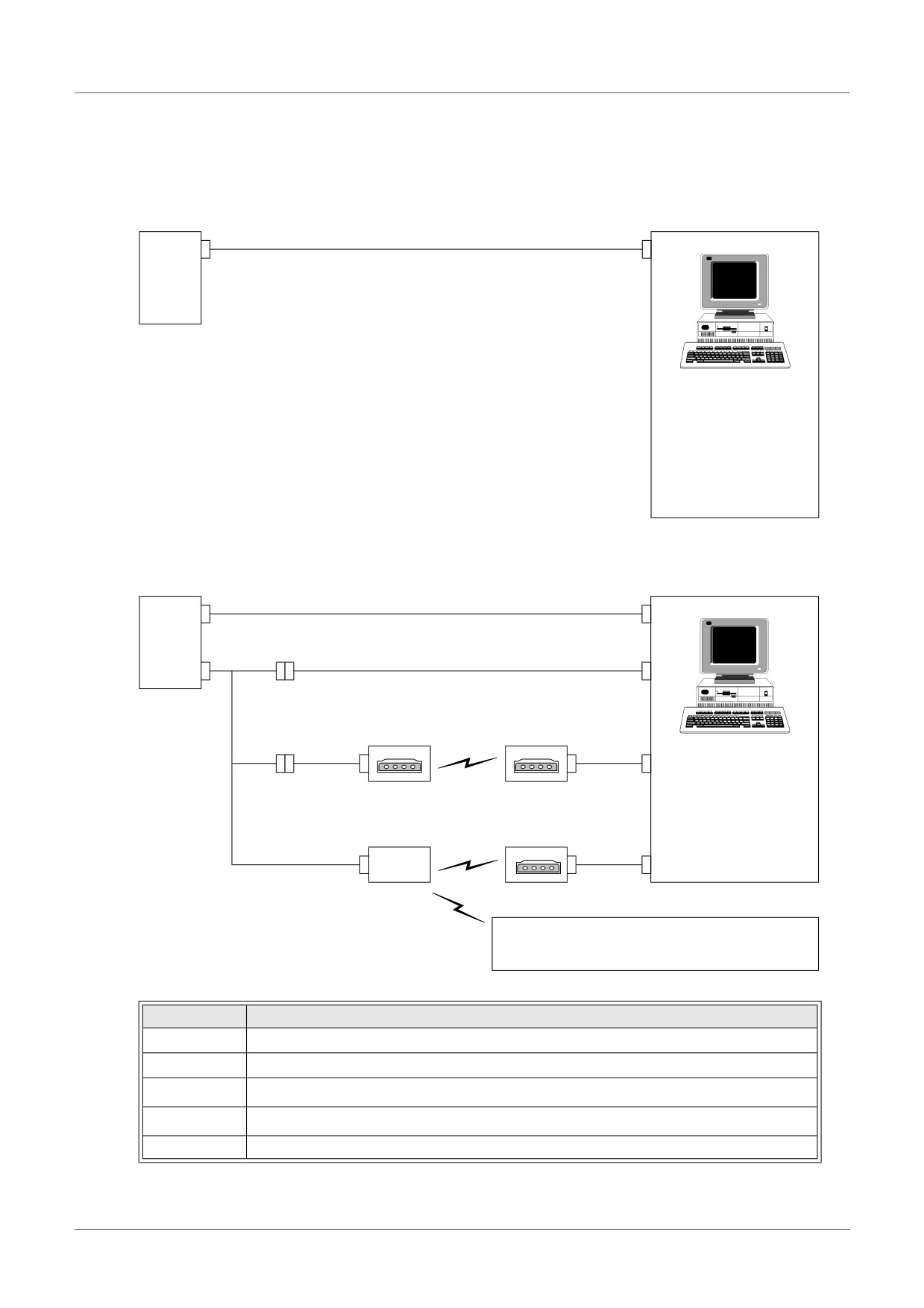
Figure 1.4: System Configuration(AL2-10MR-*)
Standard Connection to the Programming Softoware
c
α2
Series
Personal computer
- Programming Software
(AL-PCS/WIN-E)
Figure 1.5: System Configuration(AL2-14MR-*,AL2-24MR-*)
Standard Connection to the Programming Softoware
c
α2
Using Dedicated Protocol
Series
d
e
Remote Maintenance (via Telephone Line)
Normal Modem
Normal Modem
f
g
Personal computer
d
- Programming Software
(AL-PCS/WIN-E)
- Dedicated protocol
Remote Maintenance, e-Mail (via GSM)
- e-Mail application
Normal Modem
g
d
GSM
Modem
Sending SMS Message
Cellular Phone
(Supporting SMS message)
Table 1.5: System Configuration
Item
Using Cable
1
AL-232CAB
2
AL2-GSM-CAB
3
RS-232C cross cable*1
4
RS-232C straight cable for the modem*1
5
RS-232C straight cable for the modem (specified by Modem manufacturer)
*1 Further information can be found in chapter 8.
ENG-6
Introduction 1
1.5
Version Up List
Table 1.6: History of α2 Series
Version
Description
V1.00
First product
Supports the following points.
• AL2-2DA, AL2-2PT-ADP, AL2-2TC-ADP modules
V2.00
• New function blocks
ENG
AO [Analog output] and PID [PID control]
• DCF77 Radio clock
Supports the following points.
• New function blocks
SMR[Short Message Receiving] and CD[Call Detect]
• Enhanced User Program Protection
V2.20
• Enhanced Daylight Saving Time Setup
• Enhanced Dedicated Protocol Communication
• GSM SIM PIN
• Modem Initialization String
Supports the following points.
• Hour Meter backs up by EEPROM (No.197 - 200)
V3.00
• Display Buffer Read by Dedicated Protocol
• Russian language addition
1.6
Applicable Programming Software
Table 1.7: Applicable Programming Software
α2 Version
Programming Software (AL-PCS/WIN-E) Version
V1.00
V2.00 or later
V2.00
V2.30 or later
V2.20
V2.40 or later
V3.00
V2.50 or later
Note;
• AL-PCS/WIN-E versions lower than V2.00, do not communicate with the α2 series.
• AL-PCS/WIN-E versions lower than V2.30, do not use the AL2-2DA, AL2-2PT-ADP or
AL2-2TC-ADP.
ENG-7
Specifications 2
2.
Specifications
Note;
• Refer to chapter 9 about specification of the AL2-ASI-BD.
• Refer to chapter 11 about specification of the AL2-2DA.
• Refer to chapter 12 about specification of the AL2-2PT-ADP.
• Refer to chapter 13 about specification of the AL2-2TC-ADP.
2.1
Power Supply Specification
Table 2.1: Power Supply Specifications
Description
Code
Specification
AL2-***-A
100 - 240V AC~, +10% -15%, 50/60 Hz
Power Supply
AL2-***-D
24V DC, +20% -15%
Maximum Momentary Power
AL2-***-A
10ms
Failure
AL2-***-D
5ms
AL2-***-A,
≤ 6.5 A (3.5 A) < 5ms
In-rush Current
240V AC~ (120V AC~)
AL2-***-D, 24V DC
≤ 7.0 A
AL2-10MR-A, 264V AC~
4.9 W
AL2-10MR-D, 28.8V DC
4.0 W
Maximum Power
AL2-14MR-A, 264V AC~
5.5 W
Consumption
AL2-14MR-D, 28.8V DC
7.5 W
AL2-24MR-A, 264V AC~
7.0 W
AL2-24MR-D, 28.8V DC
9.0 W
AL2-10MR-A, 240V AC~
I/O all On - 3.5 W; I/O all Off - 1.85 W
AL2-10MR-A, 120V AC~
I/O all On - 3.0 W; I/O all Off - 1.55 W
AL2-10MR-D, 24V DC
I/O all On - 2.5 W; I/O all Off - 0.75 W
AL2-14MR-A, 240V AC~
I/O all On - 4.5 W; I/O all Off - 2.0 W
Typical Power Consumption
(without Special Connection
AL2-14MR-A, 120V AC~
I/O all On - 3.5 W; I/O all Off - 1.5 W
Modules)
AL2-14MR-D, 24V DC
I/O all On - 4.0 W; I/O all Off - 1.0 W
AL2-24MR-A, 240V AC~
I/O all On - 5.5 W; I/O all Off - 2.5 W
AL2-24MR-A, 120V AC~
I/O all On - 4.5 W; I/O all Off - 2.0 W
AL2-24MR-D, 24V DC
I/O all On - 5.0 W; I/O all Off - 1.0 W
AL2-***-A
Rating: 250 V 1 A
AL2-10MR-D
Type: Time Lag
Fuse
AL2-14MR-D
Rating: 250 V 500 mA
AL2-24MR-D
Type: Time Lag
ENG-8
Specifications 2
2.2
Input Specification
Table 2.2: AC Input Specifications
AC Input Specification
main unit
AL2-4EX-A2
AL2-10MR-A:
Description
I01-I06
AL2-24MR-A:
AL2-14MR-A,
EI1 - EI4
I09 - I15
ENG
AL2-24MR-A:
I01-I08
220 - 240V AC~, +10% -15%,
Input Voltage
100 - 240V AC~, +10% -15%, 50/60 Hz
50/60 Hz
0.13mA / 120V AC~*1
0.15mA / 120V AC~*1
7.5mA / 240V AC~ 50Hz
Input Current
0.25mA / 240V AC~*1
0.29mA / 240V AC~*1
9.0mA / 240V AC~ 60Hz
32kΩ (50Hz)
Input Impedance
≥ 800 kΩ
27kΩ (60Hz)
OFF → ON/ ON → OFF
≥ 80V / ≤ 40V
≥ 160V / ≤ 40V
35-85ms, 120V AC~
OFF → ON
Response
25-55ms, 240V AC~
15 - 40ms / 240V AC~
Time
35-85ms, 120V AC~
ON → OFF
50-130ms, 240V AC~
Isolation Circuit
None
Photocoupler
Operation Indication
Liquid Crystal Display
*1 Current leakage from the sensors connected to the inputs might provide enough current
to turn the controller On. Do not use two wire sensors
Table 2.3: DC Input Specifications
Description
Sink (“-” Common)
Source (“+” Common)
Input Voltage
24V DC +20% -15%
24V DC +20% -15%
AL2-10MR-D
I01 - I06
6.0mA, 24V DC
Input
main unit
AL2-14MR-D
I01 - I08
5.5mA, 24V DC
Current
AL2-24MR-D
I09 - I15
5.5mA, 24V DC
AL2-4EX
EI1 - EI4
5.4mA, 24V DC
5.4mA, 24V DC
OFF →
Current: ≥ 4.7mA / ≤ 1.1 mA
main unit
I01 - I15
Voltage: ≥ 18V / ≤ 4V
ON/
Voltage: ≤ 4V / ≥ 18V
ON →
AL2-4EX
EI1 - EI4
Voltage: ≥ 18V / ≤ 4V
Voltage: ≥ 18V / ≤ 4V
OFF
main unit
10 - 20ms
Response
Time
AL2-4EX*2
10 - 20ms
Isolation
main unit
None
Circuit
AL2-4EX
Photocoupler
Operation Indication
Liquid Crystal Display
0
*2 EI1 and EI2 in AL2-4EX can be used as High Speed Counters.
When using the High Speed Counter function, the input response time is 0.5ms or less.
ENG-9
Specifications 2
Table 2.4: Analog Input Specifications (Only AL2-***-D Type Unit)
Description
Analog Input Specification
6 (I01 - I06) : AL2 - 10MR - D
Number of Input Points
8 (I01 - I08) : AL2 - 14MR - D,AL2 - 24MR - D
Analog Input Range
0 - 500
Resolution
9 bit, 20mV (10V/ 500)
Conversion Speed
8ms
Input Voltage
0 - 10V DC
Input Impedance
142kΩ ± 5%
Overall Accuracy
± 5% (0.5V DC)
Offset Value = 0 at 0V DC
Offset/Gain
Gain Value: 0 - 10V = 0 - 500
These default values can be changed in the OffsetGain FB
Temperature Drift
± 3 LSB
ENG-10
Specifications 2
2.3
Output Specification
Table 2.5: Relay Output Specifications
Description
Relay Specification
Switched Voltage
250V AC~ or less, 30V DC or less
AL2-10MR-* (O01 - O04)
AL2-14MR-* (O01 - O06)
8A/COM
Max. Resistive Load
AL2-24MR-* (O01 - O04)
ENG
AL2-24MR-* (O05 - O09)
2A/point (4A/COM)
AL2-4EYR (EO1 - EO4)
2A/point
AL2-10MR-* (O01 - O04)
AL2-14MR-* (O01 - O06)
100,000 Cycles at 8 Amps / 240V AC~ or 24V DC
Contact Life Cycle /
AL2-24MR-* (O01 - O04)
Resistance Load
AL2-24MR-* (O05 - O09)
100,000 Cycles at 2 Amps / 240V AC~ or 24V DC
AL2-4EYR (EO1 - EO4)
Minimum Load
50mW (10mA at 5V DC)
AL2-10MR-* (O01 - O04)
249 VA (1/3 hp) / 125V AC~,
AL2-14MR-* (O01 - O06)
373 VA (1/2 hp) / 250V AC~
Max. Inductive Load
AL2-24MR-* (O01 - O04)
AL2-24MR-* (O05 - O09)
93 VA (1/8 hp) / 125V AC~,
AL2-4EYR (EO1 - EO4)
93 VA (1/8 hp) / 250V AC~
Response Time
≤ 10 ms
Operation Indication
Liquid Crystal Display
Isolation Circuit
By Relay
Table 2.6: Transistor Output Specifications (Source Type only) of AL2-4EYT
Description
Transistor Specification
Switched Voltage
5 - 24V DC (+20%, -5%)
Max. Resistive Load
1A / point (8 - 24V DC), 0.1A / point (5 - 8V DC)
Minimum Load
1.0mA
Max. Inductive Load
1A / 24V DC (24 W)
Response Time On/Off, Off/On (approx)
≤ 1 ms
Open Circuit Current Leakage
≤ 0.1mA / 24V DC
Operation Indication
Liquid Crystal Display
Isolation Circuit
Photocoupler
ENG-11
Specifications 2
2.4
General Specification
Table 2.7: Environmental and Electrical Specifications
Description
Specification
Programming Method
Function Block
Program Capacity
200 Function Blocks or 5000 bytes
Built in EEPROM (no battery backup required) or optional EEPROM
Program Storage
cassette (AL2-EEPROM-2)
Device Backup
20 Days at 25°C / 77°F (by capacitor)
RTC Backup
20 Days at 25°C / 77°F (by capacitor)
RTC Accuracy
5 s / day (25°C / 77°F)
Controller Hardware: (-25) - 55°C / (-13) - 131°F
Operating Temperature
Controller Display: (-10) - 55°C / 14 - 131°F
Storage Temperature
(-30) - 70°C / (-22) - 158°F
Conforms to IEC 68-2-6; 10-57Hz: 0.15mm Constant Amplitude
Vibration Resistance
57-150Hz: 19.6m/s2 Acceleration
- Direct Mounting
Sweep Count for X,Y,Z: 10 times (80 minutes in each direction)
Conforms to IEC 68-2-6; 10-57Hz: 0.075mm Constant Amplitude
Vibration Resistance
57-150Hz: 9.8m/s2 Acceleration
- DIN Rail mounting
Sweep Count for X,Y,Z: 10 times (80 minutes in each direction)
Conforms to IEC 68-2-27: 147m/s2 Acceleration, Action Time: 11ms
Shock Resistance
3 times in each direction X,Y, and Z
Noise Immunity
1000Vpp, 1 µs, 30 - 100Hz, tested by noise simulator
Humidity
35 - 85% Relative Humidity, no condensation
3750V AC~ > 1min per EN60730-1 between the following points:
Dielectric withstand
Power/Input Terminals and Relay Output Terminals
voltage
Relay Output Terminal and Relay Output Terminal
All Terminals and the DIN 43880 Control box or equivalent
7 MΩ at 500V DC per EN60730-1 between the following points:
Power/Input Terminals and Relay Output Terminals
Insulation Resistance
Relay Output Terminal and Relay Output Terminal
All Terminals and the DIN 43880 Control box or equivalent
Type of Action
EN60730-1, Section 6.4.3 - Type 1C (Relay Output)
Type of Action
EN60730-1, Section 6.4.3 - Type 1Y (Transistor Output)
Software Class
EN60730-1, Section H6.18 - Class A
Purpose of Control
EN60730-1, Section 2.2 - Electrical Control
Construction of Control
EN60730-1, Section 6.15 - Incorporated Control
Whether the Control is
EN60730-1, Section H2.5.7 - Electronic Control
electric
Safety Class
ΙΙ
Pollution Degree
2
Grounding
None
Electrical Isolation
Reinforced primary/secondary insulation
Operation Ambience
To be free of corrosive gases. Dust should be minimal.
Protection
IP 20
ENG-12
Specifications 2
Table 2.7: Environmental and Electrical Specifications
Description
Specification
Temperature for the Ball
75°C (167°F)
Pressure Test
Working altitude
<2000 m*1
Installation location
Inside a control panel*2
Overvoltage category
ΙΙ
ENG
EN61131-2: 2007
EMC
EN60730-1: 2011
EC Directive
EN61131-2: 2007*3
LVD
EN61010-2-201:2013*3*4
EN60730-1: 2011
Certification of UL/cUL
File number: E95239*5
Will display 4 lines of 12 characters per line, Program Run On/Off mode,
Liquid Crystal Display
Password Protection, Image Table, and Function Blocks during
programming.
*1 α2 Series Controller cannot be used at a pressure higher than the atmospheric pressure
to avoid damage.
*2 α2 Series Controller is assumed to be installed in an environment equivalent to indoor.
*3 For α2 Series Controllers manufactured before February 28th, 2018 are compliant with
EN61131-2:2007, after March 1st, 2018 are compliant with EN61010-2-201:2013.
*4 For some models manufactured after January 1st, 2018 are compliant with EN61010-2-
201:2013.
*5 AL2-ASI-BD is not complied with these standards.
Caution for compliance with LVD Directive (EN61010-2-201:2013)
• Please use the α2 Series Controller while installed in conductive shielded control panels
under a general industrial environment.
• α2 Series Controller are open-type devices that must be installed and used within
conductive control panels. Please secure the control panel lid to the control panel (for
conduction). Installation within a control panel greatly affects the safety of the system and
aids in shielding noise from the α2 Series Controller.
• For the control panel, use the product having sufficient strength, fire protectiveness and
shielding property to an installation environment.
• To an external connection port other than AC power supply terminal and AC input/output
terminal, connect the circuit separated from a dangerous voltage by a double/reinforced
insulation.
• When wiring, please insert the cable all the way in the terminal block.
• Cutoff device such as a breaker or a circuit protector should be installed in accordance with
the following precautions.
- Use EN60947-1 or EN60947-3 standards.
- Place the cutoff device so that it can be operated easily.
- Specify that the cutoff device is for this equipment.
ENG-13
Installation 3
3.
Installation
3.1
Installation Mounting Notes
The α2 Series’ safe design means the user can install it almost anywhere but please take
the following points into consideration.
• Do not install in areas with excessive or conductive dust, corrosive or flammable gas,
moisture or rain, excessive heat, regular impact shocks or excessive vibration. Do not
place in water or let water leak onto the controller.
• Do not allow debris to fall inside the unit during installation.
• Keep as far as possible from high-voltage cables and power equipment.
• The α2 Series Controller must be installed in a distribution box or a control cabinet.
• If there is the possibility of touching the α2 Series Controller inside a control panel in
maintenance, make sure to discharge to avoid the influence of static electricity.
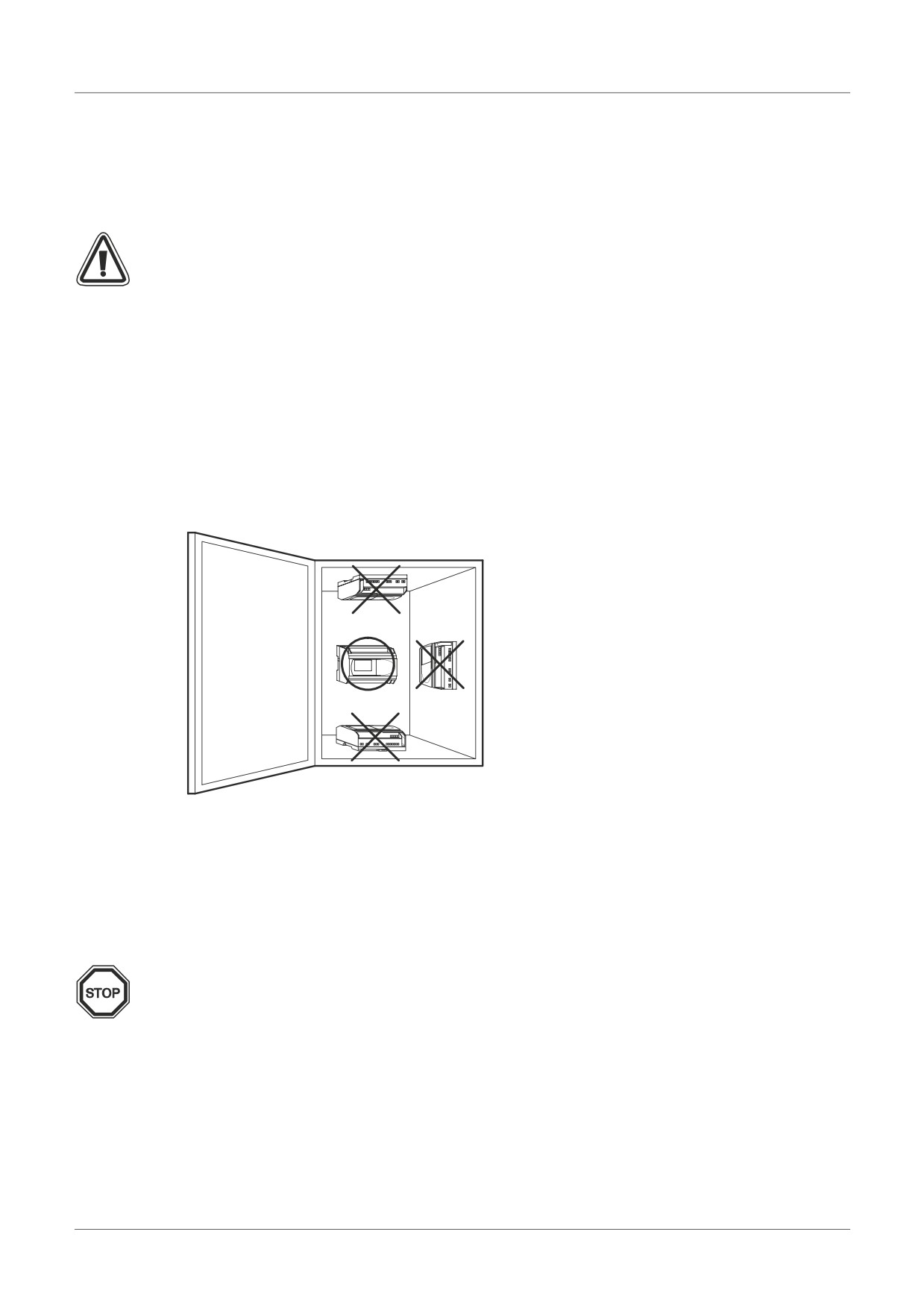
Figure 3.1: Mounting Arrengement.
• Use size M4 screws when mounting by screw holes.
• The connectors must be covered to prevent injury from contact with “live” wires.
• Leave a minimum of 10mm of space for ventilation between the top and bottom edges of
the α2 Series Controller and the enclosure walls.
• Do not disassemble the α2 Series controller.
Note;
• Refer to chapter 6 when installing or removing the AL2-EEPROM-2.
• Refer to chapter 7 when installing or removing the AL-232CAB.
• Refer to chapter 8 when installing or removing the AL2-GSM-CAB.
• Refer to chapter 9 when installing or removing the AL2-ASI-BD.
• Refer to chapter 11 when installing or removing the AL2-2DA.
• Refer to chapter 12 when installing or removing the AL2-2PT-ADP.
• Refer to chapter 13 when installing or removing the AL2-2TC-ADP.
ENG-14
Installation 3
3.2
DIN RAIL Mounting of Main Unit
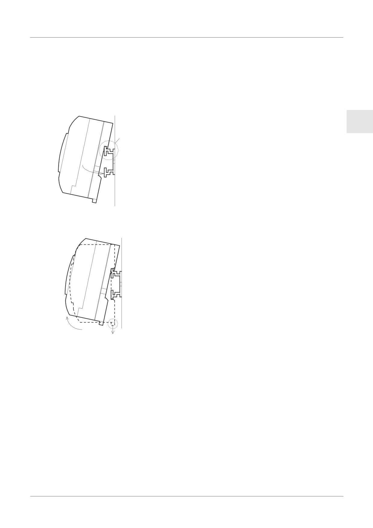
Units can be snap mounted to 35mm DIN rail (DIN EN 50022). To release pull the spring
loaded clips away from the rail and slide the unit off and up.
3.2.1
Installation
Figure 3.2: Installation
Align the upper side of the α2 DIN rail mounting groove with the
ENG
DIN rail (c) and push it onto the rail (d).
3.2.2
Remove
Figure 3.3: Remove
Pull the DIN rail hook (c) and remove the α2 series main unit(d)
ENG-15
Installation 3
3.3
Direct Mounting of Main Unit
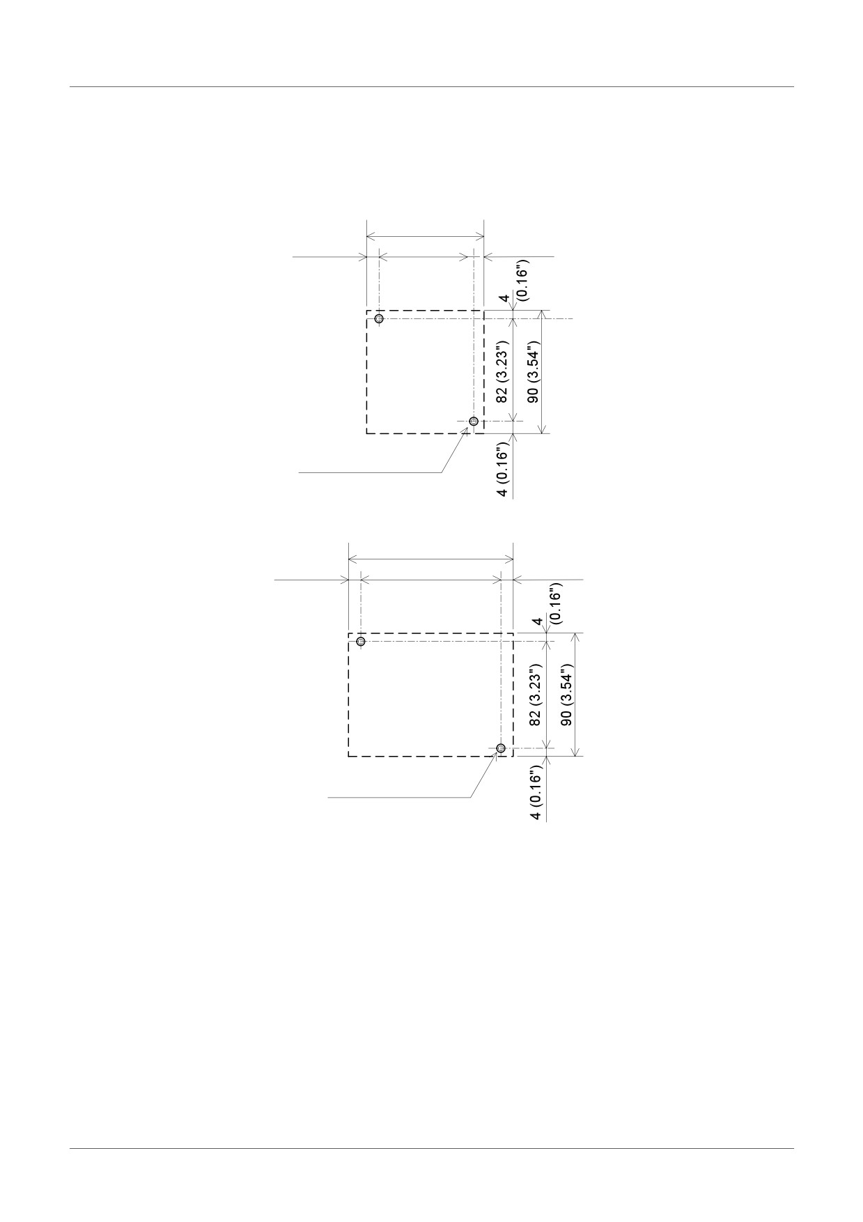
Figure 3.4: Direct Mounting
71.2 (2.8")
6 (0.24")
59.2(2.34")
6 (0.24")
AL2-10MR-*
M4 Mounting Screw
124.6 (4.91")
6 (0.24")
112.6 (4.43")
6 (0.24")
AL2-14MR-*
AL2-24MR-*
M4 Mounting Screw
ENG-16
Installation 3
3.4
Install Extension Module(AL2-14MR-*,AL2-24MR-*)
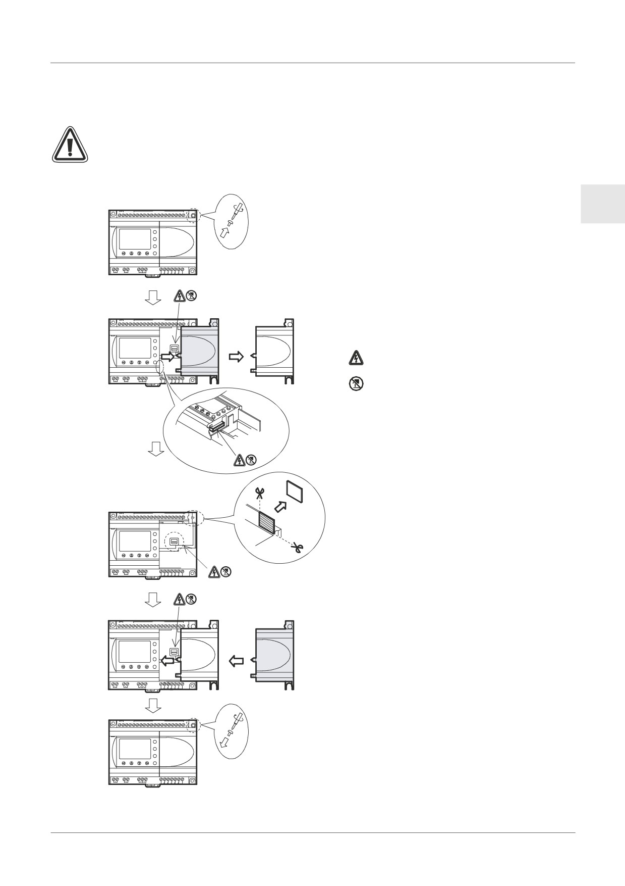
Caution;
Disconnect all terminals from the power supply before removing the cover.
Figure 3.5: Installation
1) Release screw ‘A’ and keep.
ENG
+
-
(A)
(B)
1
2
3
4
5
6
7
DC INPUT
8
9
10
11
12
13
14
15
1)
POWER
24V DC
ESC
2) Carefully remove the factory fitted
+
A
-
expansion port cover.
OK
AL2-24MR-D
RELAY
3) Cut away section ‘B’ from the α2 series
OUT1
OUT2
OUT3
OUT4
OUTPUT
OUT
5
6
7
8
9
controller main unit.
4) Attach the expansion module to the main
unit.
+
-
(A)
(B)
1
2
3
4
5
6
7
DC INPUT
8
9
10
11
12
13
14
15
2)
POWER
24V DC
5) Tighten screw ‘A’ to a torque of 0.4 N·m.
ESC
+
-
OK
: A danger of electric shock.
AL2-24MR-D
RELAYOUTPUT
5
7
8
9
OUT1
OUT2
OUT3
OUT4
OUT
: Do not touch the conductive parts of the
product directly.
B
+
-
(A)
(B)
1
2
3
4
5
6
7
DC INPUT
8
9
10
11
12
13
14
15
3)
POWER
24V DC
ESC
+
-
OK
AL2-24MR-D
OUT1
OUT2
OUT3
OUT4
RELAY
OUTPUT
OUT
5
6
7
8
9
+
-
(A)
(B)
1
2
3
4
5
6
7
DC INPUT
8
9
10
11
12
13
14
15
4)
POWER
24V DC
ESC
+
-
OK
AL2-24MR-D
OUT1
OUT2
OUT3
OUT4
RELAY
OUTPUT
OUT
5
6
7
8
9
+
-
(A)
(B)
1
2
3
4
5
6
7
DC INPUT
8
9
10
11
12
13
14
15
5)
24V DC
POWER
ESC
+
A
-
OK
AL2-24MR-D
OUT1
OUT2
OUT3
OUT4
RELAY
OUTPUT
OUT
5
6
7
8
9
ENG-17
Wiring 4
4.
Wiring
Note;
• Refer to chapter 9 when wiring the AL2-ASI-BD.
• Refer to chapter 11 when wiring the AL2-2DA.
• Refer to chapter 12 when wiring the AL2-2PT-ADP.
• Refer to chapter 13 when wiring the AL2-2TC-ADP.
4.1
Installation Wiring Notes
The wiring of α2 Series has been designed to be safe and easy. A technician or engineer
trained in the local and national electrical standards should perform all tasks associated
with the electrical wiring of the α2 Series controllers. Turn OFF the Power before
performing any wiring operations.
• Input and output cables should not be run through the same multicore cable or share the
same wire.
• Do not lay input/output cables near high voltage power cables.
• Input and Output cable length must be less than 30m (98' 5").
Allow for voltage drop and noise interference with input/output lines used over an extended
distance. Please use wire that is properly sized for the current load.
The terminal will accept a 3 mm flathead screwdriver.
ENG-18
Wiring 4
4.2
Wire Size
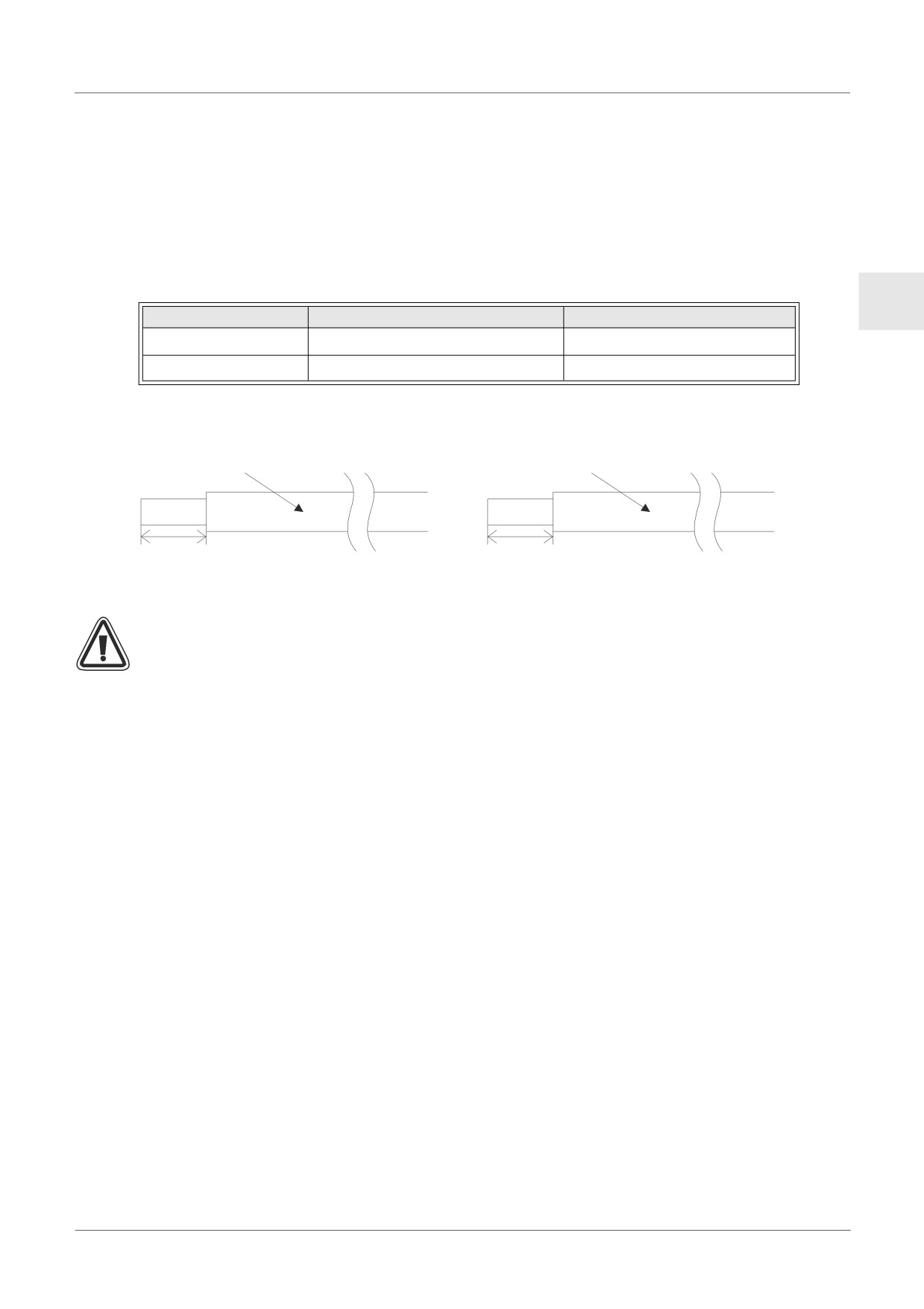
Wire of the Inputs and Outputs using the following wire. Strip the wire to the following length
(See Table 4.1 and Figure 4.1). Please unscrew the terminal to its widest position before
inserting a wire. Insert the wire completely into the terminal to ensure that a proper connection
can be made.
The terminals will accept a 3mm flathead screwdriver.
Table 4.1: Wire Size
ENG
Wire Size
Strip Wire Length
Main Unit
26 - 12 AWG (0.13 - 3.31mm2)
7mm ± 0.5mm
Extension Module
24 - 14AWG (0.2 - 2.5mm2)
6mm ± 0.5mm
Figure 4.1: Wire Size
Main unit
Extension module
26 -12 AWG
24 -14 AWG
7mm(0.276") ± 0.5mm(0.02")
6mm(0.236") ± 0.5mm(0.02")
Temperature Rating: Min. 80 °C (176 °F)
Temperature Rating: Min. 80 °C (176 °F)
Note;
• To avoid damaging the wire, tighten to a torque of 0.5 - 0.6 N⋅m.
• Please do not use tin, solder, or any other substance on the stripped wire that might
cause the wire strand to break.
- Stranded cable:
Remove sheath, twist core wires, then connect cable (or use a crimp terminal).
- Single cable:
Remove sheath, then connect cable.
ENG-19
Wiring 4
4.3
Power Supply
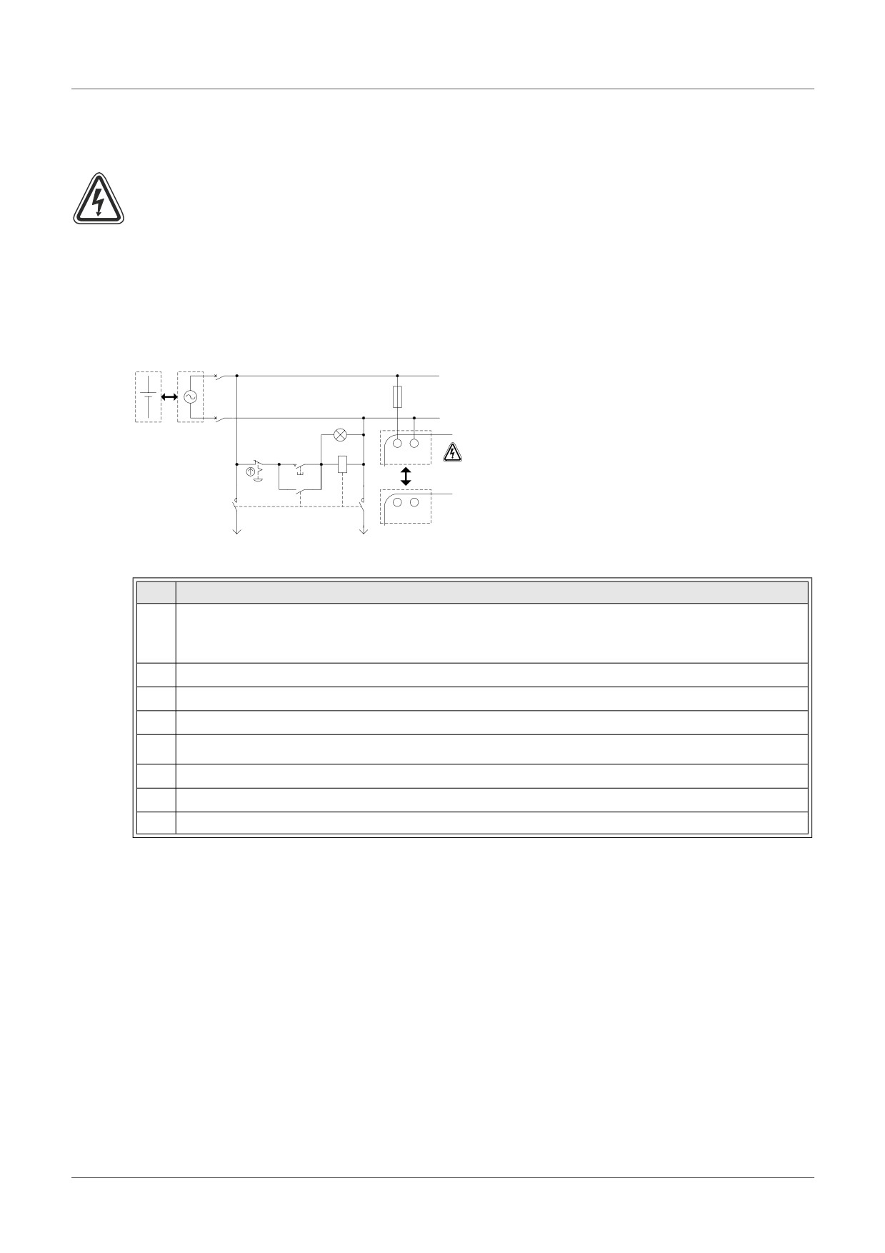
• When wiring AC supplies the “Live” cable should be connected to the “L” terminal and
the “Neutral” cable should be connected to the “N” terminal. Do NOT connect the “Live”
wire to the “N” terminal, the user might receive a dangerous shock on powerup.
• When wiring DC supplies the “positive” cable should be connected to the “+” terminal
and the negative cable should be connected to the “-” terminal. On no account should
the power supply terminals be connected to any other terminal on the unit. DC Power
Supply units should be capable of providing 4 Amperes of current to the controller.
Figure 4.2: Recommended Power Input Wiring Diagram
c
+
L
f
N
e
d
h
MC
"L" and "N" terminals are
Start
L N
not reversible.
g
MC
i
i
+ -
j
j
Table 4.2: Recommended Power Wiring
Ref.
Item Description
Power supply
1
AL2-***-A: 100-240V AC~, 50/60Hz
AL2-***-D: 24V DC
2
Circuit isolation device
3
Power ON pilot indicator
4
Circuit protection device - Limit to 1.0A
5
α2 main unit
6
Emergency stop
7
Magnetic switch contact
8
Power supply for loads
ENG-20
Wiring 4
4.4
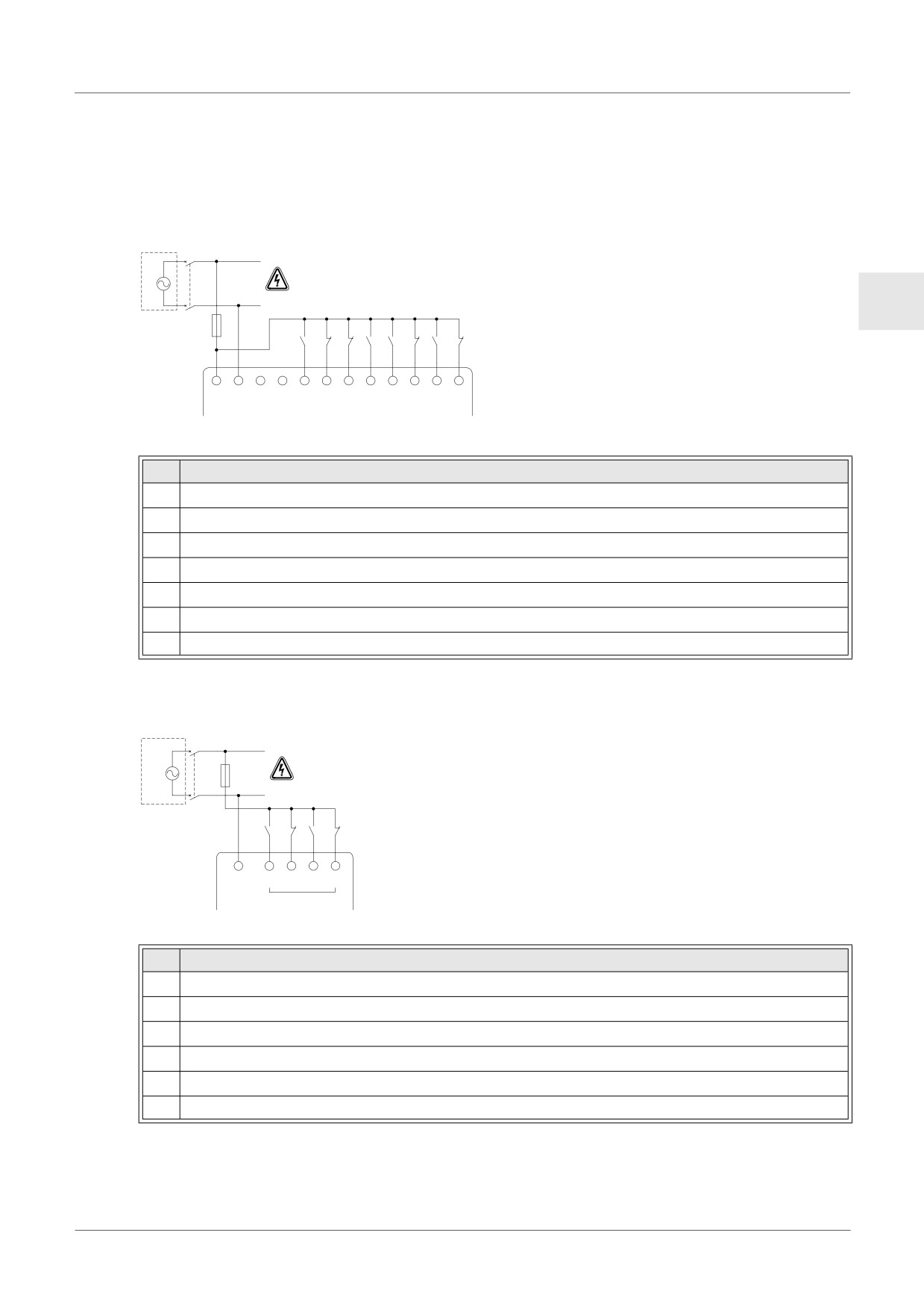
AC Power Supply and Input Wiring
4.4.1
AC Power Supply and Input Wiring
Figure 4.3: AC Power Supply and Input Wiring Diagram
c
d
"L" and "N" terminals
L
are not reversible.
N
ENG
e
i
L N
g
1
2
3
4
5
6
7
8
f
INPUTSh
Table 4.3: AC Power Supply and Input Wiring
Ref.
Item Description
1
AC power supply, 100 - 240V AC~, 50/60Hz
2
Circuit isolation device
3
Circuit protection device - Limit to 1.0 Amp
4
AC power terminals
5
Unused terminals
6
Input terminals
7
Digital input switches
4.4.2
AL2-4EX-A2 Input Wiring
Figure 4.4: AL2-4EX-A2 Input Wiring Diagram
c d
L
"L" and "N" terminals
e
are not reversible.
N
h
f
COM
EI1 EI2
EI3 EI4
(N)
g
Table 4.4: AC Power Supply and Input Wiring
Ref.
Item Description
1
AC power supply, 220 - 240V AC~, 50 / 60Hz
2
Circuit isolation device
3
Circuit protection device - Limit to 1.0 Amps
4
COM (N) terminal
5
Input terminals
6
Digital input switches
ENG-21
Wiring 4
4.5
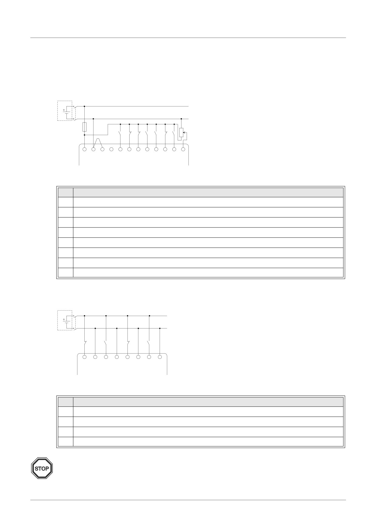
DC Power Supply and Input Wiring
4.5.1
DC Power Supply and Source (“+” Common) Input Wiring Diagram
Figure 4.5: DC Power Supply and Source (“+” Common) Input Wiring Diagram
c d
j
e
h
+
-
(A) (B)
1
2
3
4
5
6
7
8
f g
INPUTS i
Table 4.5: DC Power Supply and Source (“+” Common) Input Wiring
Ref.
Item Description
1
DC power supply, 24V DC
2
Circuit isolation device
3
Circuit protection device - Limit to 1.0A
4
DC power terminals
5
Sink/Source input wiring terminals
6
Sensor input switches
7
Input terminals
8
Analog input
4.5.2
AL2-4EX Source (“+” Common) Input Wiring Diagram
Figure 4.6: AL2-4EX Source (“+” Common) Input Wiring Diagram
c d
f
f
f
f
EI1
EI1
EI2
EI2
EI3
EI3
EI4
EI4
(+)
(-)
(+)
(-)
(+)
(-)
(+)
(-)
e e e e
Table 4.6: DC Power Supply and Source (“+” Common) Input Wiring
Ref.
Item Description
1
DC power supply, 24V DC
2
Circuit isolation device
3
Input terminals
4
Sensor input switches
Note:
Each input terminal (EI1 - EI4) can be used as either Source input or Sink input.
ENG-22
Wiring 4
4.5.3
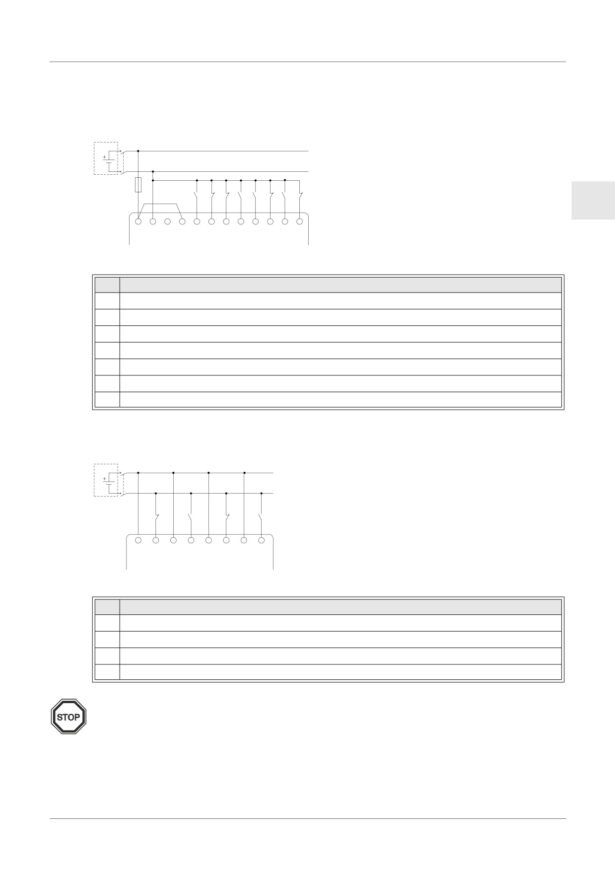
DC Power Supply and Sink (“-” Common) Input Wiring Diagram
Figure 4.7: DC Power Supply and Sink (”-” Common) Input Wiring Diagram
c d
e
h
ENG
+
-
(A) (B)
1
2
3
4
5
6
7
8
f g
INPUTSi
Table 4.7: DC Power Supply and Sink (“-” Common) Input Wiring
Ref.
Item Description
1
DC power supply, 24V DC
2
Circuit isolation device
3
Circuit protection device - Limit to 1.0 Amps
4
DC power terminals
5
Sink/Source input wiring terminals
6
Sensor input switches
7
Input terminals
4.5.4
AL2-4EX Sink (“-” Common) Input Wiring Diagram
Figure 4.8: AL2-4EX Sink (”-” Common) Input Wiring Diagram
c d
f
f
f
f
EI1
EI1
EI2
EI2
EI3
EI3
EI4
EI4
(+)
(-)
(+)
(-)
(+)
(-)
(+)
(-)
e e e e
Table 4.8: DC Power Supply and Sink (“-” Common) Input Wiring
Ref.
Item Description
1
DC power supply, 24V DC
2
Circuit isolation device
3
Input terminals
4
Sensor input switches
Note:
Each input terminal (EI1 - EI4) can be used as either Source input or Sink input.
ENG-23
Wiring 4
4.6
Output Relay and Transistor Wiring
4.6.1
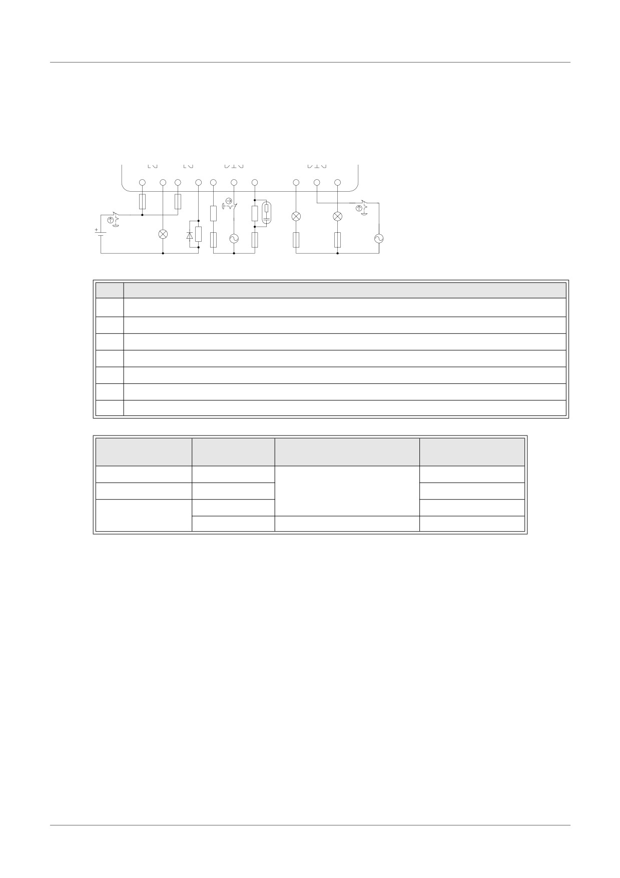
Relay Output Wiring Diagram main unit (AC and/or DC)
Figure 4.9: Relay Output Wiring Diagram main unit (AC and/or DC)
c
OUT1
OUT2
OUT3 OUT4
OUT5 OUT6
d
d
g
g
f
f
e
g
e
e
e
e
e
i
i
h
f
f
f
f
Table 4.9: Relay Output Wiring main unit (AC and/or DC)
Ref.
Item Description
1
α2 main unit
2
Mutually exclusive outputs
3
Output devices
4
Circuit protection device (See Table 4.10)
5
Emergency stop
6
DC power supply
7
AC power supply
Table 4.10: Relay Output Circuit Protection Table
Number of
Circuit Protection
Model
Max. Resistive Load
Output
(Fuse)
AL2-10MR-*
O01-O04
≤ 10A / Circuit
AL2-14MR-*
O01-O06
8A/common
≤ 10A / Circuit
O01-O04
≤ 10A / Circuit
AL2-24MR-*
O05-O09
2A/point (4A/common)
≤ 3A / Circuit
ENG-24
Wiring 4
4.6.2
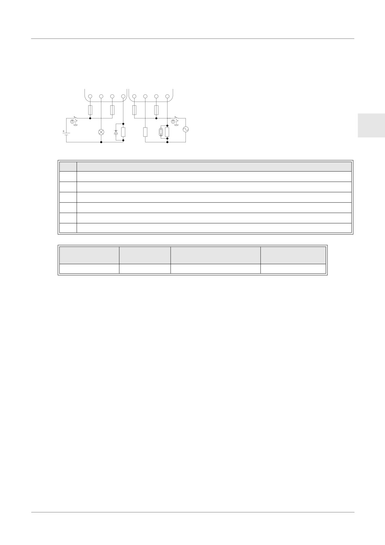
Relay Output Wiring Diagram AL2-4EYR (AC and/or DC)
Figure 4.10: Relay Output Wiring Diagram AL2-4EYR (AC and/or DC)
EO1
EO2
EO3
EO4
f f f f
e
e
e
e
d
d
h
c
g
ENG
g g
g
Table 4.11: Relay Output Wiring AL2-4EYR (AC and/or DC)
Ref.
Item Description
1
DC power supply
2
Emergency stop
3
Circuit protection device (Fuse: ≤ 3A)
4
Mutually exclusive outputs
5
Output devices
6
AC power supply
Table 4.12: Relay Output Circuit Protection Table
Number of
Circuit Protection
Model
Max. Resistive Load
Output
(Fuse)
AL2-4EYR
EO1-EO4
2A/common
≤ 3A / Circuit
ENG-25
Wiring 4
4.6.3
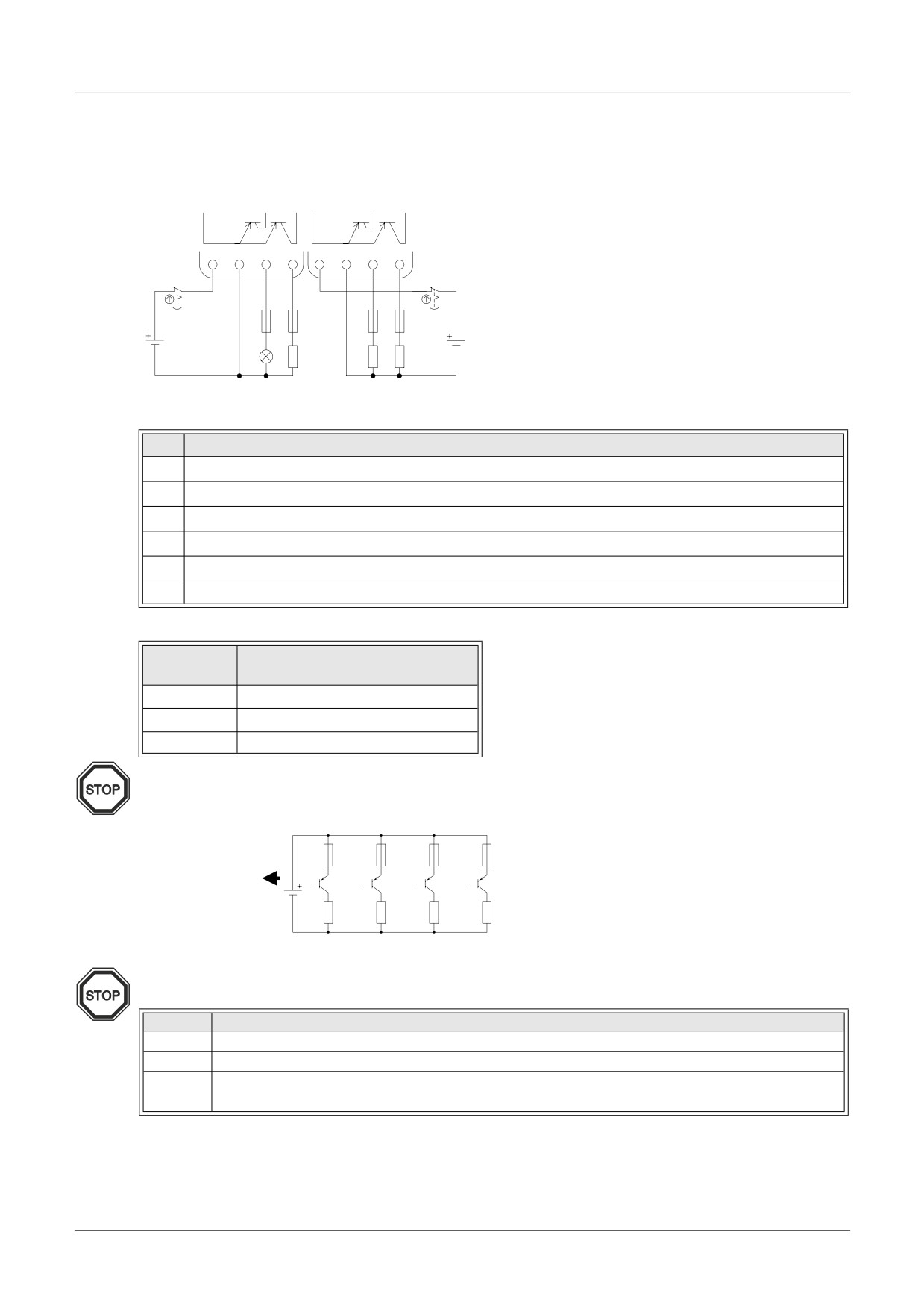
Transistor Output (Source or “+” Common Only) Wiring Diagram AL2-4EYT
Figure 4.11: Transistor Output (Source/ “+” Common Only) Wiring Diagram AL2-4EYT
+
-
EO1 EO2
+
-
EO3 EO4
f
f
d
d
e
e
e
e
c
h
g
g
g
g
Table 4.13: Transistor Output Wiring
Ref.
Item Description
1
DC Power Supply: 24V DC
2
Emergency Stop
3
Circuit Protection Device - See Table 4.14 for Specifications
4
Power Supply Terminal
5
Output Devices
6
DC Power Supply: 12V DC
Table 4.14: Transistor Output Circuit Protection Table
Circuit
Circuit Protection (Fuse)
Voltage
5V DC
< 0.3A/Circuit
12V DC
< 2.0A/Circuit *1
24V DC
< 2.0A/Circuit *1
*1 Power Source capacity ≥ Fuse size × 2
Figure 4.12: Example Fuse Size Calculation
Fuse
Fuse
Fuse
Fuse
1A
1A
1A
1A
12V, 8A
(8A ≥ 1A × 2 × 4)
O01
O02
O03
O04
Note;
Table 4.15: Output Terminal Notes
Volt
Output Terminal Notes
5
Each circuit can contain from one output terminal up to every output terminal.
12-24
Each circuit can contain from one output terminal up to every output terminal.
Using any combination of 5 Volt, 12 Volt, and 24 Volt outputs can be accomplished on the
5,12,24
same α2 Series Controller if separate circuits are used for each voltage level.
ENG-26
Terminal Layout 5
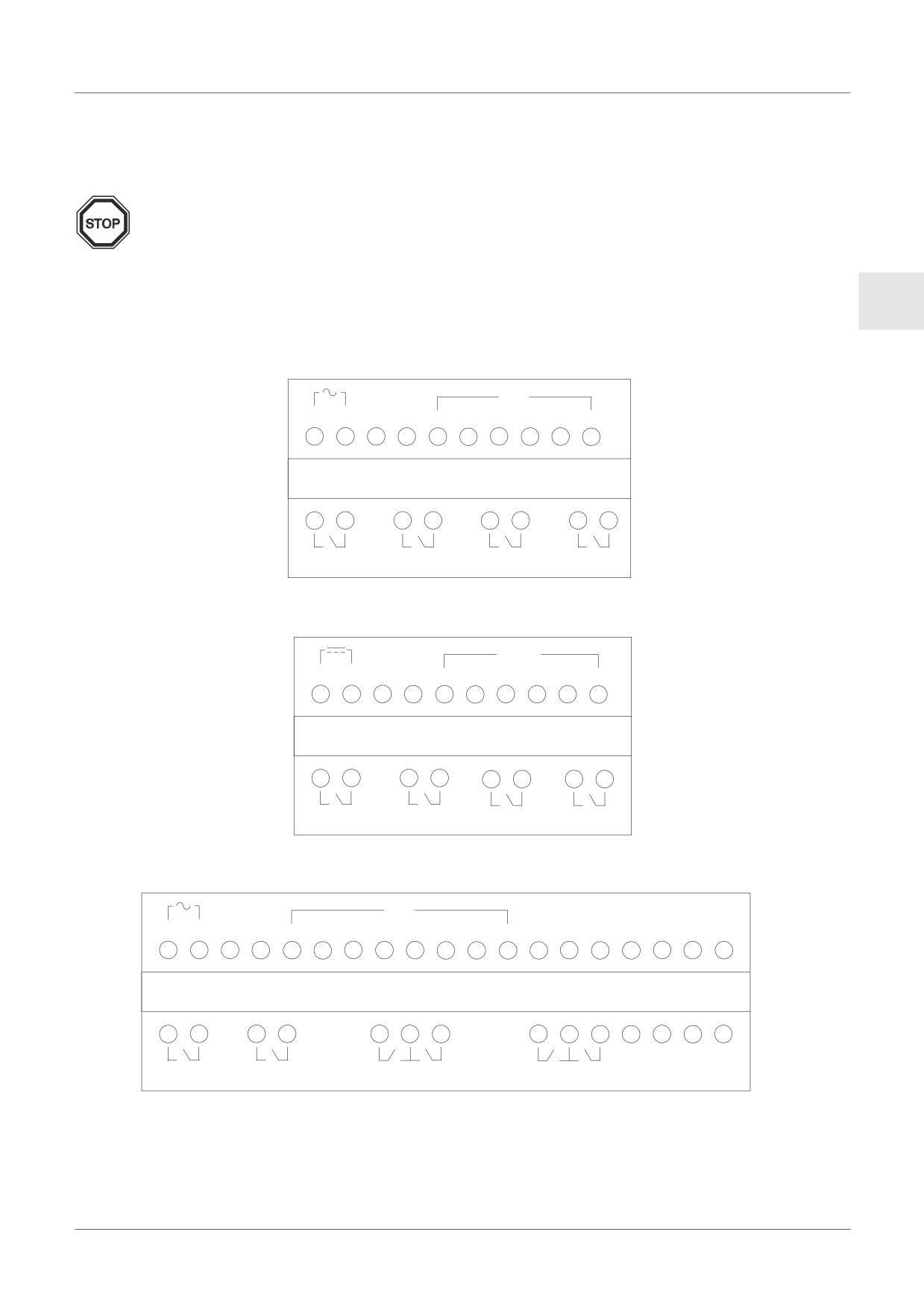
5.
Terminal Layout
Note;
• Refer to chapter 9 about terminal layout of the AL2-ASI-BD.
• Refer to chapter 11 about terminal layout of the AL2-2DA.
• Refer to chapter 12 about terminal layout of the AL2-2PT-ADP.
ENG
• Refer to chapter 13 about terminal layout of the AL2-2TC-ADP.
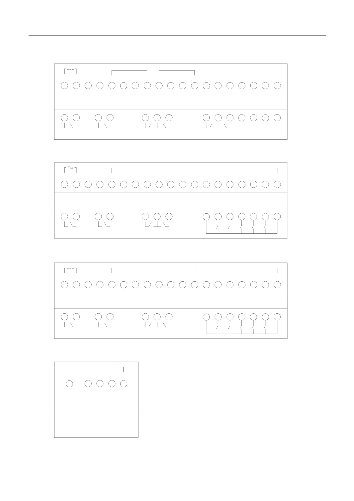
Figure 5.1: AL2-10MR-A, AC Input, Relay Output
IN
L N
1
2
3
4
5
6
AL2-10MR-A
OUT1
OUT2
OUT3
OUT4
Figure 5.2: AL2-10MR-D, DC Input, Relay Output
IN
+
-
(A)
(B)
1
2
3
4
5
6
AL2-10MR-D
OUT1
OUT2
OUT3
OUT4
Figure 5.3: AL2-14MR-A, AC Input, Relay Output
IN
L N
1
2
3
4
5
6
7
8
AL2-14MR-A
OUT1
OUT2
OUT3 OUT4
OUT5 OUT6
ENG-27
Terminal Layout 5
Figure 5.4: AL2-14MR-D, DC Input, Relay Output
IN
+
-
(A)
(B)
1
2
3
4
5
6
7
8
AL2-14MR-D
OUT1
OUT2
OUT3 OUT4
OUT5 OUT6
Figure 5.5: AL2-24MR-A, AC Input, Relay Output
IN
L N
1
2
3
4
5
6
7
8
9
10
11
12
13
14
15
AL2-24MR-A
5
6
7
8
9
OUT1
OUT2
OUT3 OUT4
OUT
Figure 5.6: AL2-24MR-D, DC Input, Relay Output
IN
+
-
(A)
(B)
1
2
3
4
5
6
7
8
9
10
11
12
13
14
15
AL2-24MR-D
5
6
7
8
9
OUT1
OUT2
OUT3 OUT4
OUT
Figure 5.7: AL2-4EX-A2, 220 - 240V AC Input
IN
COM(N) EI1 EI2 EI3 EI4
AL2-4EX-A2
ENG-28
Terminal Layout 5
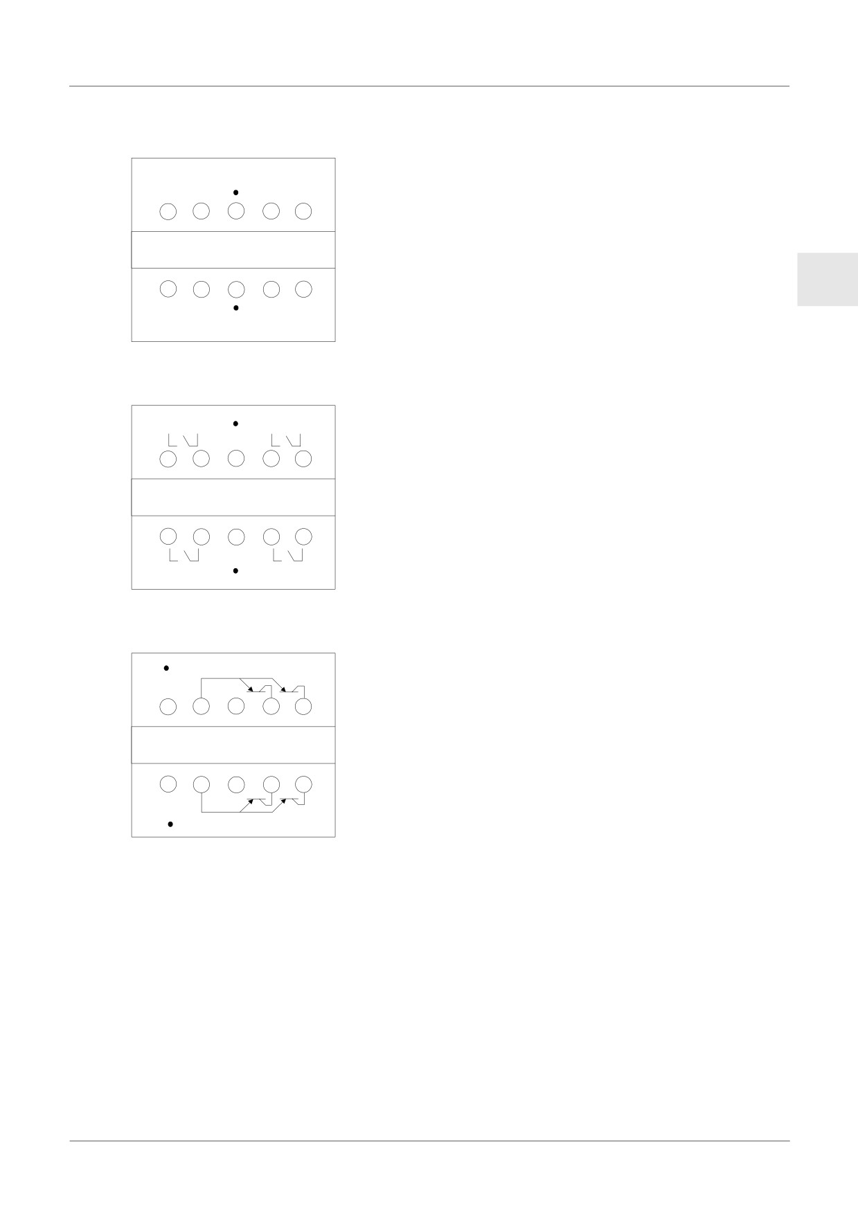
Figure 5.8: AL2-4EX, DC Input
EI1
EI2
+
-
+
-
AL2-4EX
ENG
+
-
+
-
EI3
EI4
Figure 5.9: AL2-4EYR, Relay Output
EO1
EO2
AL2-4EYR
EO3
EO4
Figure 5.10: AL2-4EYT, Transistor Output
+
- EO1 EO2
AL2-4EYT
+
-
EO3 EO4
ENG-29
AL2-EEPROM-2 6
6.
AL2-EEPROM-2
The AL2-EEPROM-2 memory cassette is for use only with the α2 series controller
(Model: AL2-**M*-*).
Caution
• Persons trained in the local and national electrical standards must replace the memory
cassette.
• Turn off the power supply when installing or removing the memory cassette.
• Replace the cover after removing the memory cassette.
• When installing the connector cover or the memory cassette of α2 series, be careful not
to pinch your finger.
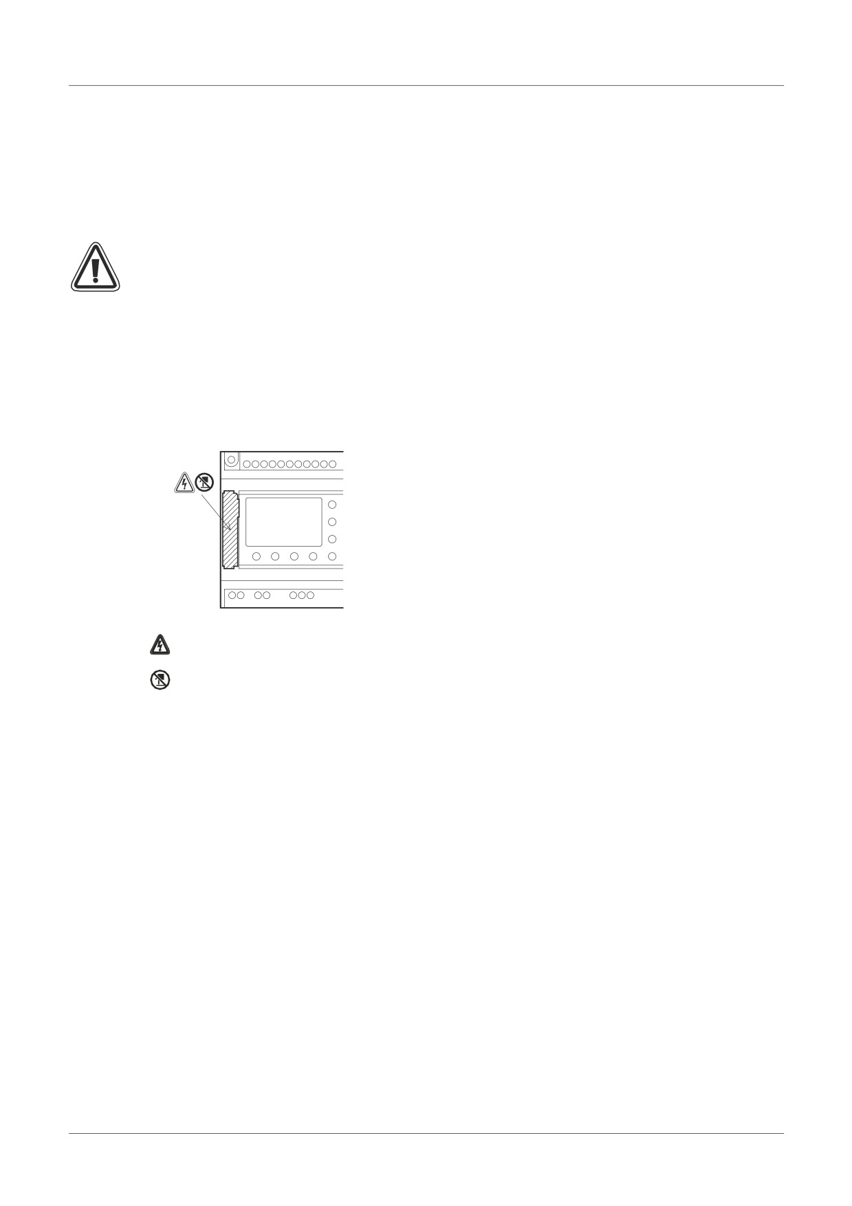
• DO NOT touch the following part when removing the cover or memory cassette.
: A danger of electric shock.
: Do not touch the conductive parts of the product directly.
ENG-30
AL2-EEPROM-2 6
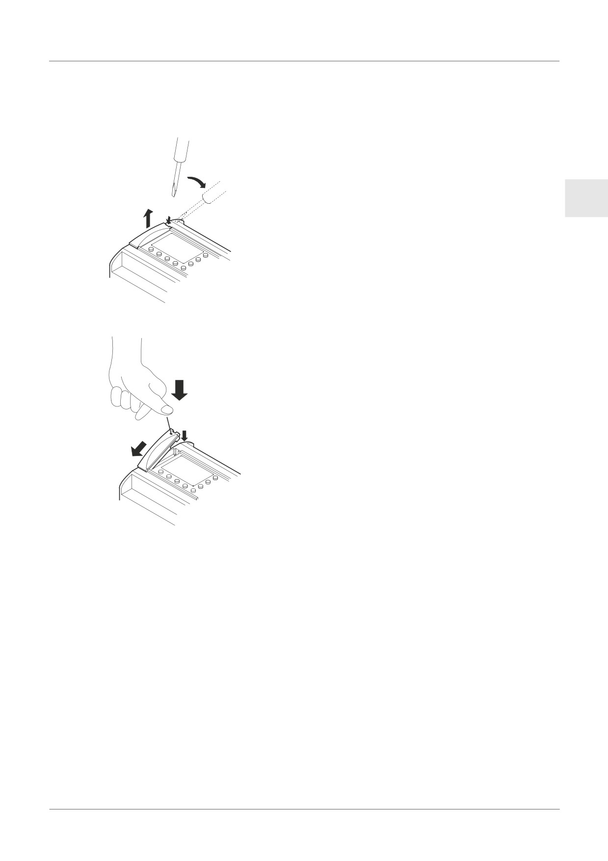
6.1
Installation
1) Remove the cover or the memory cassette
ENG
2) Install on the cover or the memory cassette
ENG-31
//////////////////////////////////////////