Amtrak. Service Standards Manual for Train Service and On-Board Service Employees (Version 6, 2011) - page 3
• Allow the automatic Fire Suppression System
to activate, which occurs after a two-minute
delay from initial alarm.
• Acknowledge the alarm and deactivate Fire
Suppression System, after confirming no fire
exists, with the Multifunction Display No. 1
(MFD1), or the fire supp. INHIBIT pushbutton.
• Once a Fire Suppression System has been
deactivated, the Fire Control Unit (FCU)
must be reset to get back the detection mode.
• Manually activate the Fire Suppression
System, after confirming a fire exists, with
the FIRE SUPP. ACTIVATION pushbutton.
• The fire control unit bypass switch, on the
propulsion electrical cubicle, is used to bypass
the Fire Suppression System when a false fire
alarm has been triggered. (It must be used only
when it is confirmed that no fire exists.)
• The automatic Fire Suppression System is
deactivated when the Fire Control Unit is
bypassed.
c)
Get to the nearest Fire Extinguisher located in
the Emergency Equipment compartment.
•
Any Dry Chemical Fire Extinguisher on the
train is effective on all types of fires: electrical,
cloth or grease.
•
Remove Fire Extinguisher from the cabinet by
unlatching the metal strap.
•
Lift and carry Fire Extinguisher by the handle
•
Approach the source of the fire and determine
if the fire is controllable.
•
To operate the Fire Extinguisher follow the
instructions on the extinguisher and squeeze
the handle levers spraying the Extinguisher in
a side-to-side motion at the base of the fire
until the fire is out.
•
If one Fire Extinguisher is not enough, you
may have to evacuate the car (or engine).
Remember; evacuate the car (or engine) ONLY
if staying in it would mean a continuing threat
to the people inside. Protect yourself and others
from overexposure to smoke and fumes.
•
Once the seal on the Fire Extinguisher has
been broken, the extinguisher must be
removed from service and recorded in the
“Record of Defect and Repair - MAP 21A”
(NRPC 2775) form.
Service Standards Manual No. 6
1-49
7.
Emergency On-Board Police Activity
On-train employees should use the “Emergency
On-Board Police Activity Announcements” from
Chapter 10 “On-Board Announcements and Signage”
to instruct passengers on appropriate action during
times of on-board police activity in an emergency
situation, but only at the direction of the Conductor.
C.
Non-Emergency Evacuation -
Non-Station Train-To-Train Passenger
Transfer - NEC
(Refer to “Electrical Operating Instructions” (AMT-2),
regarding the use of a jumper cable to neutralize the
difference in electrical current for trains on adjacent
tracks.)
1.
General Non-Emergency Evacuation Instructions
a)
Safety and injury prevention is critical during the
transfer process.
b) The Conductor is in charge of the train and will
conduct a job briefing to instruct all crewmembers
as to each employee’s responsibilities during
the train-to-train transfer of passengers. All
On-Board Service employees are to take their
direction from the conductor.
c)
Use the train’s P.A. system; if possible, to relay
instructions to passengers. Set the P.A. to LOCAL
to only communicate with the passengers in the
present car.
d) Inform the Conductor of passengers requiring
special assistance (i.e., mobility impaired or medical
conditions). The Conductor will notify the Train
Dispatcher of any additional assistance that is
required.
e)
As directed by the Conductor, the LSA is to secure
their work area, and then move to a location on
the train where they can provide assistance to the
passengers during the transfer process.
f)
Once each train’s doorways are properly positioned,
the Conductors and Engineers of both trains
must ensure that Three-Point Protection has been
provided consisting of:
• Slack has been adjusted first, followed by the
train and engine brake being applied.
• Throttle must be in idle position, or controller
in off position, and then place the reverser in
neutral position.
1-50
Passenger Train Emergency Preparedness
• Shut down and isolate HEP from the providing
locomotive, if applicable.
• Engineer must confirm to the requesting
employee that the “Three-Point Protection”
has been provided.
g)
After Three-Point Protection has been provided,
follow these steps if needed.
• Jumper cables are prohibited between trains
that have one or more wheels derailed.
• In electrified territory, pantographs do not need
to be lowered when a jumper cable is used
during a non-station transfer of passengers.
HEP should remain on, if possible.
• In third rail territory the power must be
de-energized before the transferring of passengers.
h) Once the passenger transfer has been completed,
the following should occur under normal
circumstances:
• Assistant Conductors from the disabled train
should be assigned to the receiving train to
accompany the transferred passengers.
• Assistant Conductors from the disabled train
should practice service recovery and lend
assistance to the receiving on-train crew with
passenger luggage, information, etc.
• The disabled train's Conductor and Engineer
will remain with the disabled train in anticipation
of receiving movement instructions.
i)
Service Recovery efforts can be applied as
appropriate for the service and time. This would
be decided by the Division(s) in conjunction with
CNOC and the Customer Service Desk.
2.
Passenger Transfer Between Trains Without A Jumper
Cable Or Transfer Bridge
In the event of a Passenger Transfer Between Trains
Without a Jumper Cable or Transfer Bridge, On-Train
Crews must follow these instructions in addition to
all of the instructions listed in Section 2.C.1 “General
Non-Emergency Evacuation Instructions” of this
chapter..
a) The Conductor on the disabled train will determine
the doorway location(s) for the transfer.
Depending on conditions, more than one location
can be used to expedite the transfer of passengers
and should be considered whenever possible.
b) The exit doorway of the disabled train MUST
NOT be positioned directly across from the
entrance doorway of the receiving train.
Service Standards Manual No. 6
1-51
Doorways must be staggered to prevent electrical
shock by minimizing the opportunity for passengers
to make simultaneous contact with both trains.
Non-Acela Express trains should use step boxes
to shorten the distance of the last step to the
ground. Acela Express trains will use the portable
folding stairs (located on the first and last car of
each trainset).
c)
Passengers should be transferred, one car at a
time, starting with the car having the designated
exit doorway and then proceeding to each
subsequent car on the train.
d) An employee must remain with any passenger
who is unable to physically transfer until that
passenger has been moved.
e)
Crew members from both trains should be
positioned in the vestibule area and on the ground
at the bottom of the steps or ladder, and on the
ground between the trains, to assist with the transfer
of both passengers and passengers’ luggage/carry-on
items. Do the following in this order:
• First - transfer exiting passenger’s luggage and
carry-on items from the disabled train to the
receiving train.
• Second - assist the passenger down the steps or
ladder of the disabled train onto the ground.
• Third - assist the passengers towards and up
the steps or ladder of the receiving train;
reuniting the passengers with their possessions.
Passenger’s carry-on baggage is to be transferred
with the passenger.
f)
Passengers should be cautioned not to touch both
trains at the same time and crew members should
take precautions to prevent this from happening.
3.
Passenger Transfer Between Trains With A Jumper
Cable, Without A Transfer Bridge
In the event of a Passenger Transfer Between Trains
With a Jumper Cable, Without a Transfer Bridge,
On-Train Crews must follow these instructions in
addition to all of the instructions listed in Section
2.C.1 “General Non-Emergency Evacuation
Instructions”of this chapter.
a) The Conductor on the disabled train will determine
the doorway location(s) for the transfer.
Depending on conditions, more than one location
1-52
Passenger Train Emergency Preparedness
can be used to expedite the transfer of passengers
and should be considered whenever possible.
b) The exit doorway of the disabled train must be
positioned as closely as possible to be directly
across from the entrance doorway of the receiving
train if the clearances between trains permit.
• Non-Acela Express trains should use step
boxes to shorten the distance of the last step
to the ground.
• Acela Express trains will use the portable folding
stairs (located on the first and last car of each
trainset).
c)
The jumper cable, approximately 12 feet long
with insulated alligator-type clamps at each end,
is to be attached to each train car body (e.g., grab
iron, door, stirrup, etc.) on each train so that a
good connection is made between the two trains.
• When attaching the clamp to an Acela Express
use the car body or door support bracket, not
the grab iron. (The grab irons on Acela
Express equipment are insulated from the car
body and will not neutralize the current
between trains.)
• The jumper cable should be positioned near
the transfer location(s) yet out of the way from
the transfer process.
d) Passengers should be transferred, one car at a
time, starting with the car having the designated
exit doorway and then proceeding to each
subsequent car on the train.
e)
An employee must remain with any passenger
who is unable to physically transfer until that
passenger has been moved.
f)
Crew members from both trains should be
positioned in the vestibule area and on the ground
at the bottom of the steps or ladder, and on the
ground between the trains, to assist with the transfer
of both passengers and passengers’ luggage/
carry-on items. Do the following in this order:
• First - transfer exiting passenger’s luggage and
carry-on items from the disabled train to the
receiving train.
• Second - assist the passenger down the steps or
ladder of the disabled train onto the ground.
• Third - assist the passengers towards and up
the steps or ladder of the receiving train,
Service Standards Manual No. 6
1-53
reuniting the passenger with their possessions.
Passengers’ carry-on baggage is to be
transferred with the passengers.
g) Do NOT allow passengers to step or jump from
one vestibule platform or set-of-steps to another.
h) When the transfer is complete, disconnect the
jumper cables and store in designated location.
4.
Passenger Transfer Between Two Trains With A
Jumper Cable And Transfer Bridge
In the event of a Passenger Transfer Between Two Trains
With a Jumper Cable and Transfer Bridge, On-Train
Crews must follow these instructions in addition to all
of the instructions listed in Section 2.C.1 “General Non-
Emergency Evacuation Instructions” of this chapter.
a)
The Conductor on the disabled train will determine
the doorway location(s) for the transfer.
Depending on conditions, more than one location
can be used to expedite the transfer of passengers
and should be considered whenever possible.
b) The exit doorway of the disabled train must be
positioned directly across from the entrance
doorway of the receiving train to use the Transfer
Bridge.
c)
The jumper cable, approximately 12 feet long
with insulated alligator-type clamps at each end,
is to be attached to each train car body (e.g., grab
iron, door, stirrup, etc.) on each train so that a
good connection is made between the two trains.
• When attaching the clamp to an Acela Express
use the car body or door support bracket, not
the grab iron. (The grab irons on Acela Express
equipment are insulated from the car body and
will not neutralize the current between trains.)
• The jumper cable should be positioned near
the transfer location(s) yet out of the way from
the transfer process.
d) If a jumper cable is not available, the transfer can
still be made utilizing the bridge, as long as pre-
cautions are taken to prevent passengers from
simultaneously touching both trains.
e)
The Transfer Bridge is designed for placement in
the vestibules of trains on adjacent tracks thus
providing a walkway with handrails across the
gap between trains.
1-54
Passenger Train Emergency Preparedness
f)
The component pieces of the Transfer Bridge are:
•
1 - black leather carrying case with handles
•
1 - transfer bridge with two hinged ramp
“wings” (W24" x L76" extended)
•
2 - two-piece handrails with netting attached
•
2 - two-piece sets of foam handrail packing
g)
The Transfer Bridge should not be used if the
distance between trains is greater than 66 inches.
Use the yellow tape markings on the jumper
cable, which are spaced 66 inches apart, as a
guide to determine if the distance between trains
is greater than 66 inches.
h) The Conductor on the disabled train will remove
the Transfer Bridge and jumper cable from its
storage location and move them to the vestibule
where the transfer will be made.
i)
The Conductor on the disabled train will
communicate the doorway location to the receiving
Train Conductor, and assist in spotting the receiving
train so that both train doorways are located
directly across from one another.
j)
Unfold the Transfer Bridge and secure the ends in
the open position using the hook-and-eye fixtures
near the hinges. Tilt the bridge on its side and
slide it toward the crew members on the other
train.
k) When the Transfer Bridge is inside the door-ways
of both trains, and past the side edge clearance
marking (yellow & black striped tape), set it
down in the vestibules and ensure it is securely
in place.
l)
Assemble the two side rails and netting placing
them in the support holes on the sides of the
Transfer Bridge. (As weight is placed on the
bridge, the tension causes tightening of the
handrails in the support holes.)
m) Begin the transfer process with the passengers by
handing their luggage across to the crew member(s)
on the rescue train and then support the passengers
as they cross the bridge. Have them pick up their
luggage and proceed away from the transfer area.
n) Passengers should be transferred, one car at a
time, starting with the car having the designated
exit doorway and then proceeding to each
subsequent car on the train.
Service Standards Manual No. 6
1-55
o) When the transfer is complete, disassemble the
handrails and Transfer Bridge, store in the carrying
case and place in the storage compartment.
p) Passengers in wheelchairs, which do not fit onto
the transfer bridge, must be assisted or carried
across by employees. (Refer to Chapter 11
“Assisting Passengers with Disabilities”)
5.
Passenger Transfer Between Amfleet Equipment (or
Amfleet to Acela Equipment) With A Jumper Cable
And G2 Transfer Bridge.
In the event of a Passenger Transfer Between Two
Trains With a Jumper Cable and G2 Transfer Bridge,
On-Train Crews must follow these instructions in
addition to all of the instructions listed in Section
2.C.1 “General Non-Emergency Evacuation
Instructions” of this chapter.
a) The Conductor on the disabled train will determine
the doorway location(s) for the transfer. Depending
on conditions, more than one location can be
used to expedite the transfer of passengers and
should be considered whenever possible.
b) Train positioning should give priority for
transferring passengers in wheelchairs. Move
the Transfer Bridge to the vestibule nearest to
where the wheelchair passenger(s) is located.
c) The exit doorway of the disabled train must be
positioned directly across from the entrance
doorway of the receiving train to use the G2
Transfer Bridge.
d) The jumper cable, approximately 12 feet long
with insulated alligator-type clamps at each end,
is to be attached to each train car body (e.g., grab
iron, door, stirrup, etc.) on each train so that a
good connection is made between the two trains.
When attaching the clamp to an Acela Express
train, attach it to the car body or door support
bracket, not the grab iron. (The grab irons on
Acela Express equipment are insulated from the
car body and will not neutralize the current
between trains.)
e) The G2 Transfer Bridge is designed for placement
in the vestibules of trains on adjacent tracks thus
providing a walkway with handrails across the
gap between trains.
1-56
Passenger Train Emergency Preparedness
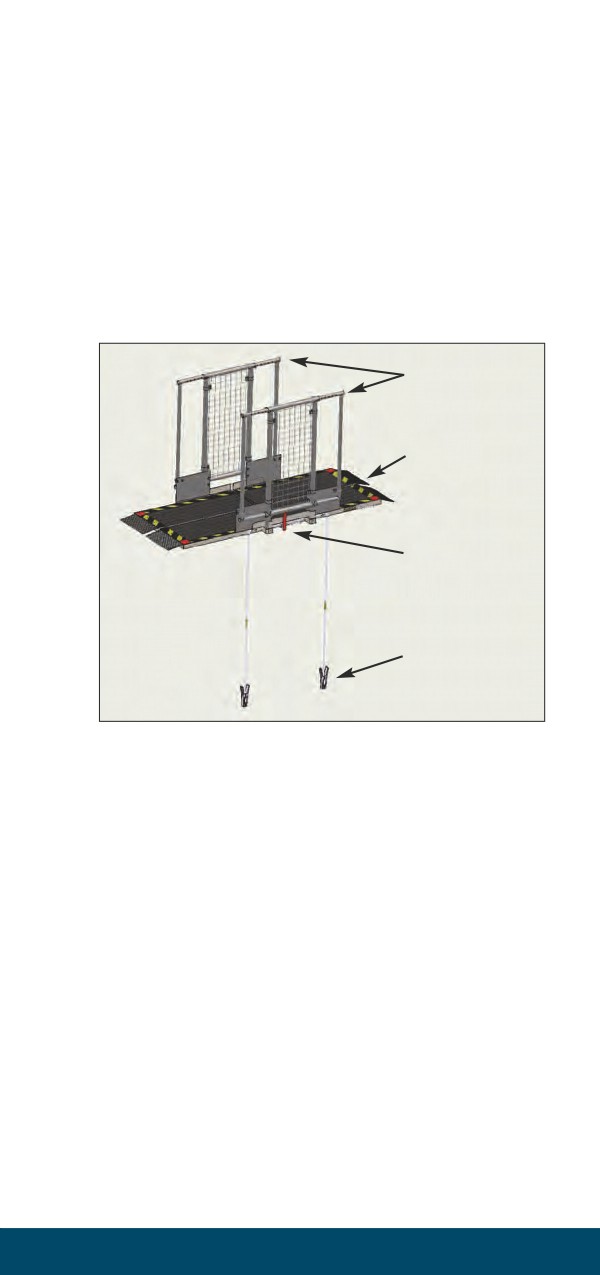
f) The component pieces of the G2 Transfer Bridge
are: (Refer to Figure 1-2)
•
1 - carrying case with handles and wheels (this
contains the transfer bridge)
•
1 - carrying case with handles (this contains the
railings)
•
1 - transfer bridge with four hinged ramp
“wings” (W30" x L76" extended)
•
2 - one-piece handrails
•
1 - Jumper Cable with Safety Lock Bar
Handrails
Transfer Bridge
Safety Lock Bar
Jumper Cable
Figure 1-2 - Example view of assembled G2 Transfer Bridge
g) The G2 Transfer Bridge should not be used if the
distance between trains is greater than 69 inches
or without the Jumper Cable with Safety Lock
Bar. Use the yellow tape markings on the jumper
cable, which are spaced 69 inches apart, as a guide
to determine if the distance between trains is
greater than 69 inches.
h) The Conductor on the disabled train will remove
the G2 Transfer Bridge and jumper cable from its
storage location and move them to the vestibule
where the transfer will be made.
i) The Conductor on the disabled train will
communicate the doorway location to the
receiving train Conductor, and assist in spotting
the receiving train so that both train doorways
are located directly across from one another.
Service Standards Manual No. 6
1-57
j)
Deploy the G2 Transfer Bridge and secure as
follows:
Watch out for pinch points! Use Personal
Protective Equipment when assembling the bridge.
•
Position the wheeled bag in the aisle adjacent to
the vestibule with the pull handle near the door.
•
Remove the Transfer Bridge and Jumper
Cable with Safety Lock Bar.
•
Remove the bag from the pathway.
•
With an employee positioned on the ground,
attach the Jumper Cable between the trains at
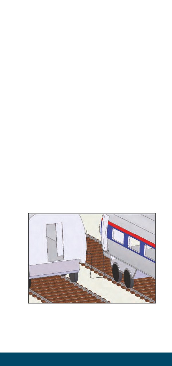
stirrups or grab irons. (Refer to Figure 1-3)
•
Note the location of the arrows on the Transfer
Bridge.
•
Move the Transfer Bridge into the vestibule
with the arrows facing the adjacent train.
(Refer to Figure 1-4)
•
Separate the Velcro safety handles used for
carrying the bridge while folded.
•
Carefully unfold the Transfer Bridge (one fold).
(Refer to Figure 1-5)
•
Flip the entire Transfer Bridge over. (Refer to
Figure 1-6)
•
Unfold the second section.
•
The Transfer Bridge should still be folded
lengthwise. (Refer to Figure 1-7)
•
Re-attach the Velcro safety handles to keep
the bridge from unfolding for safer handling.
•
Slide the Transfer Bridge to the adjacent train
with handles on the top edge and the assistance
of an employee on the ground. (Refer to
Figure 1-8)
•
Unfold the Transfer Bridge into the flat position.
(Refer to Figure 1-9)
•
The employee on the ground must insert the
Safety Lock Bar, handle up, into the hinge slot,
assist with the installation of the handrails,
and then return to the train to assist with the
transfer process.
k) When the G2 Transfer Bridge is inside the doorways
of both trains, and past the side edge clearance
marking (red indicator blocks), set it down in the
vestibules and ensure it is securely in place.
l) Assemble the handrails to the G2 Transfer Bridge
as follows: (Refer to Figure 1-10)
1-58
Passenger Train Emergency Preparedness
• Remove the handrails from the storage bag.
• Remove the storage bag from the pathway.
• Attach the railings by inserting the railing
posts into the post pockets on the transfer
bridge with the sliding safety panels toward the
transfer bridge.
• Extend the railings as needed to fill the gap
between the cars and pin them in place.
m) Begin the transfer process with the passengers
by handing their luggage across to the crew
member(s) on the rescue train and then support
the passengers as they cross the G2 Transfer
Bridge. Have the passenger pick up their luggage
and proceed away from the transfer area.
n) When transferring at two locations, passengers
should be transferred one car at a time at each
location starting with the car having the designated
exit doorway and then proceeding to each
subsequent car on the train.
o) When the transfer is complete, disassemble the
handrails and G2 Transfer Bridge. Make sure all
of the components, including the jumper cable,
are placed in the carrying case and returned to
the designated storage compartment.
p) Refer to Chapter 11 “Assisting Passengers with
Disabilities” for accommodating passengers that
may not be covered by these procedures.
Figure 1-3 - Remove jumper cable from transfer bridge bag and connect
to metal car body of both train cars involved in the transfer.
Service Standards Manual No. 6
1-59
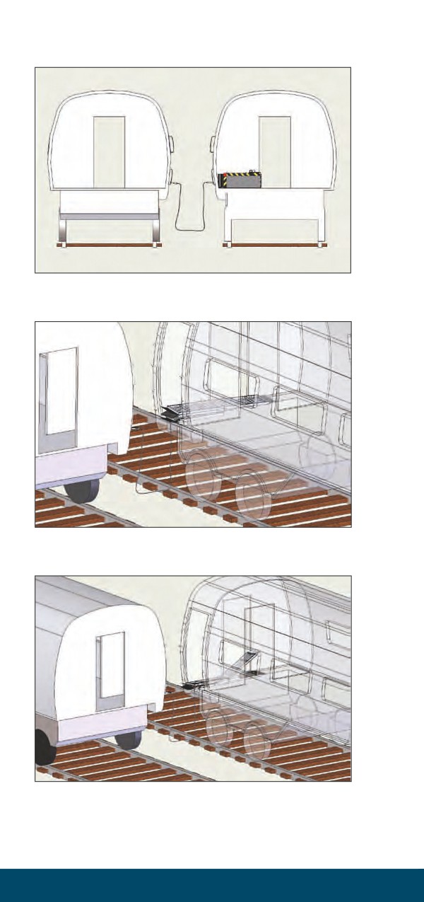
Figure 1-4 - Remove transfer bridge from bag, standing it on its side. Have
railing mounts facing upward and flap plates toward the outside door.
Figure 1-5 - Turn transfer bridge 90˚ and carefully unfold top section
(one fold) as shown.
Figure 1-6 - Flip transfer bridge over 180˙ and unfold 2nd side making
transfer bridge flat on floor surface.
1-60
Passenger Train Emergency Preparedness

Figure 1-7 - Stand transfer bridge on its side with railing mounts upward.
The transfer bridge connecting hinges should be toward the outside door.
Figure 1-8 - Transfer bridge shown deployed to 2nd car in upright position.
Hinged end must be fed to car #2 first with railing mounts facing up.
Figure 1-9 - Unfold transfer bridge to flat position and insert
Safety Lock Bar with red handle up.
Service Standards Manual No. 6
1-61
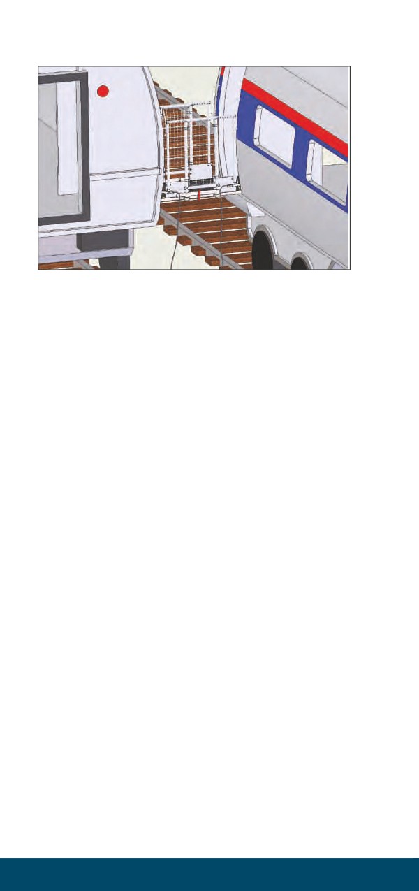
Figure 1-10 - Assemble railing and attach to railing post holder
mounts as shown.
Take all precautions necessary to reduce risk of
injury to employees and passengers.
6.
Acela-Folding Stairs
a)
Locate Folding Stairs.
• There are two (2) folding stairs, one (1) located
on each end of the trainset, in a storage compart-
ment under the vestibule of the first car adjacent
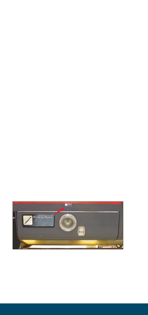
to the power car (A small gray decal showing
an icon of stair steps and the wording “Folding
Stairs” is located above the storage compartment
door.) (Refer to Figure 1-11)
• Folding stairs can be accessed from either the
right or left side of the train.
• Approximately 8’ of clearance from the side of
the train is required to remove the folding
stairs from storage compartment.
• Two crew members are needed to assemble the
folding stairs for use. (Crew members need to be
aware that the storage compartment is unprotected
from the elements allowing dirt to cover all
assembly instruction on both the lower door
panel and the stairway. The stairs should be
wiped down, if possible, before passenger use.)
b) Open Upper Storage Compartment Door.
• Open the upper storage compartment door by
pulling the release latch located on the front of
the door next to the light.
• Lift the storage compartment door to the open
position ensuring that the door safety bar is
1-62
Passenger Train Emergency Preparedness
locked in the open position to prevent the door
from closing unexpectedly. (Refer to Figure 1-12)
c)
Open and Remove Lower Storage Compartment
Door.
• Open the lower storage compartment door by
releasing the two (2) side latches. (The latch is
mounted on the carbody, not the door, next to
the safety cable door bracket.)
• Pushing the short release lever down on the
latch will open the lower storage compartment
door. (Both side latches should be released at the
same time.)(Refer to the inset in Figure 1-13)
• The two (2) safety cables located on each side
of the lower storage compartment door will
prevent the door from falling off the rear hinge.
(The rear hinge is a two (2) piece hinge that is
not connected together.) (Refer to Figure 1-13)
• With two employees, unclip both safety cables,
lift the lower door off the rear hinge and set
aside out-of-the-way. (Inside the lower storage
compartment door is a decal with the folding
stairs assembly instructions, which may or may
not be visible due to the accumulation of dirt.)
d) Remove Folding Stairs From Compartment.
• Unlock the center hold-down clamp that
secures the folding stairs by pushing the red
handle towards the center of the car. (Refer to
Figure 1-14)
• Once the center clamp is released, two crew
members can slowly pull the folding stairs,
straight out, placing the stairs on the ground.
• When pulling the folding stairs out, watch for
pinch points. (If the folding stairs will not slide
out easily, try jiggling side-to-side or up-and-
down to get past the obstruction.)
• If the folding stairs cannot be removed from
this side of the car, try sliding stairs out from
the other side, if clearances permit.
e)
Close Upper Storage Compartment Door. (The
light on the door could be helpful if nighttime
assembly is required.)
f)
Position Folding Stairs.
• When the folding stairs are removed from the
storage compartment, they will be in the face-up
position. (Small numbered assembly decals are
located at strategic points on the stairs that
Service Standards Manual No. 6
1-63
correspond to the large instructional decal located
inside the lower storage compartment door.)
• The hook assembly on the end of the folding
stairs must be positioned towards the car.
g)
Removal of Handrails.
• Using two employees, turn the folding stairs
over in the face-down position exposing the
two handrails.
• Remove the one (1) retaining pin that secures
the handrails to the back of the stairs.
• After lifting the handrails out of the storage
brackets, reinsert the retaining pin.
• Set the handrails in a location away from the
present work area.
• Using two employees, turn the folding stairs
back over to the face-up position.
h) Extend Hook Assembly.
• Extend the two (2) hook assemblies located at
the top of the stairs.
• Remove the two (2) retaining pins, one (1) from
each stair side rail, pull the hook assemblies
outward approximately 7” and reinsert the
retaining pins back into the stair side rails. (If
needed, jiggle the hook assembly to get the
retaining pin holes to properly align.)
i)
Extend Feet Assembly.
• Extend the two (2) feet assemblies located at
the bottom of the stairs.
• Remove the two (2) retaining pins, one (1) from
each stair side rail pulling the feet assemblies
outward. (The feet can be extended independently
in 2” increments, up to a total of 10”, depending
on the terrain.)
• When the feet have been set, reinsert the
retaining pins back into the stair side rails.
(If needed, jiggle the hook assembly to get the
retaining pin holes to properly align. The feet
can also be adjusted once the ladder has been
installed on the car.)
j)
Securing Stairs to Car.
• Using two employees, carefully lift the folding
stairs into position securing to the car. (Refer
to Figure 1-15)
• The locking pins, located in the center of both
hook assemblies, must be inserted into the
mounting holes located on the outer edge of
1-64
Passenger Train Emergency Preparedness
the vestibule threshold. (Refer to the inset in
Figure 1-15)
• The locking pins must be inserted all the way
into the holes, allowing the hook assembly to
sit flush on the vestibule threshold.
k) Level Stair Steps.
• Using two employees, both employees should
simultaneously have one hand securely holding
the back of a step while their other hand
removes the retaining pin from the stair side
rail. (There are two (2) retaining pins, one (1)
on each side of the stairs.)
• Begin unfolding the steps, watching for pinch
points, until the steps are level.
• Once the steps have been adjusted, insert the
retaining pin to lock the step into position.
(Refer to Figure 1-16)
l)
Position Handrail Support Brackets.
• Remove the two (2) retaining pins from the
four (4) handrail support brackets that are
secured against the stair side rails. (There are
two (2) handrail support brackets located on
each side of the folding stairs secured with one
(1) retaining pin per side.)
• Raise all four (4) handrail support brackets
into an upright position.
m) Install Handrails.
• When installing the handrails on to the handrail
support brackets, ensure that the end of the
handrail with the long overhang is towards the
top of the stairs and the end with the short
overhang is at the bottom of the stairs.
• The handrail pegs must be inserted all the way
into the handrail support brackets. (Because
there is no device to secure the handrails to the
top of the handrail support brackets, handrails
can easily come off if a passenger should lift-up
on the handrails. Crew members should be
positioned on both sides of the stairs to prevent
the handrails from pulling out of the top of the
handrail support brackets and assist passenger
using the stairs.)
n) Using Folding Stairway.
• Attach folding stairway to any open vestibule
doorway on the train. (Depending on ground
conditions, the vestibule above the stairway storage
Safety & Security
1-65
compartment may not be the best location to
position the folding stairs.)
• When assisting passengers, only one person
should be on the stairway at a time.
(Passengers with special needs may need a
crew member next to them for assistance when
using the stairway to prevent a slip or fall.)
• Crew members should verbally inform all
passengers that only one person should use
the stairs at a time.
• Remind passengers to use the handrails and to
“Watch Their Step”.
• If further evacuation instructions are needed at
this time, make sure all passengers understand
what is expected of them and answer all questions.
o) Storage of Folding Stairs.
• To disassemble the folding stairway for storage
follow steps b-m in the reverse order.
• Ensure that the handrails are returned to the
storage area on the back of the steps.
• All retaining pins must be properly installed to
secure all of the stairway components in a
locked position.
• The stairs must be inserted into the storage
compartment in the face-up position and locked
into position with the center hold-down clamp.
• Reattach the lower storage compartment door
including the two (2) safety cables.
• Ensure that the upper storage compartment
door is securely latched in the closed position.
Figure 1-11 - Upper storage compartment door, latch and decal
1-66
Passenger Train Emergency Preparedness
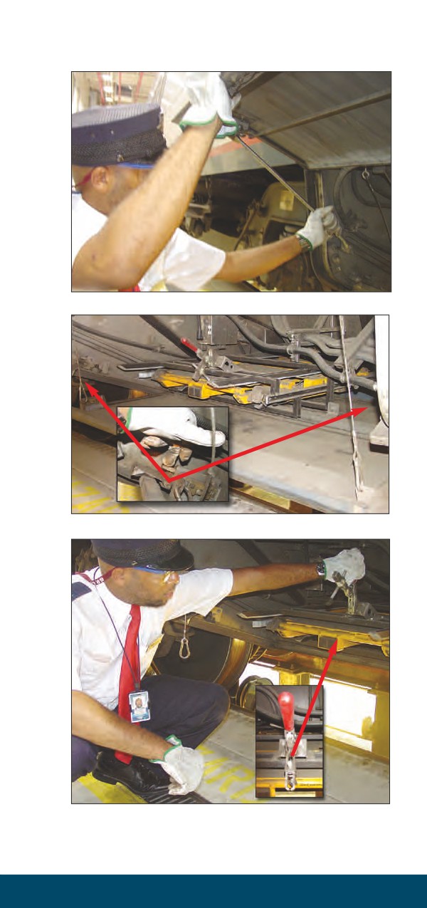
Figure 1-12 - Secure the door safety bar
Figure 1-13 - Lower storage compartment latches and safety cables
Figure 1-14 - Release folding stairs hold-down clamp
Service Standards Manual No. 6
1-67
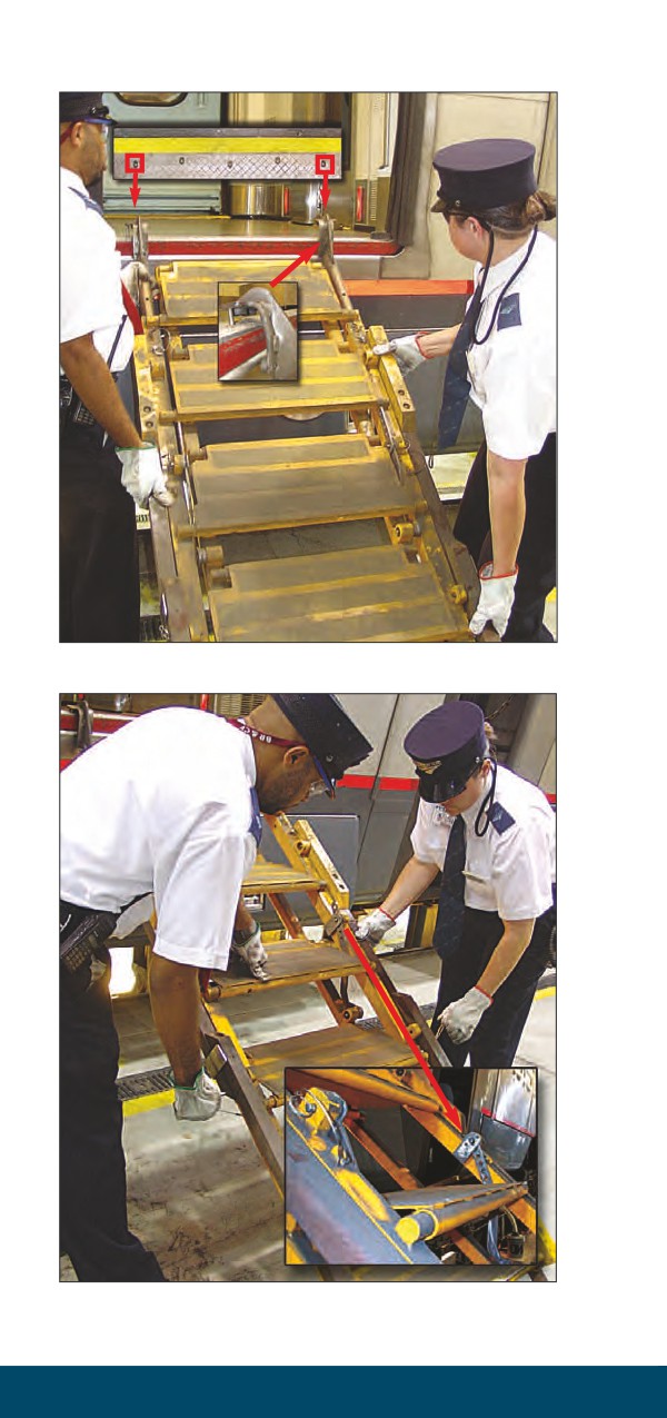
Figure 1-15 - Secure folding stairs to car body
Figure 1-16 - Level stair steps
1-68
Passenger Train Emergency Preparedness
D. Emergency Evacuation
1.
General Emergency Evacuation Instructions
a)
Remain Calm.
b) Remember that you will be looked upon for
leadership and guidance in unforeseen and
emergency situations.
c)
Notify the train service operating crew members
that you need urgent help by using the exact
words “immediate assistance”.
d) The Conductor or a designated Train Service
employee will make emergency announcements
from Chapter 10 “On-Board Announcements and
Signage” as required.
e)
Be prepared to provide evacuation instructions
and guidance to passengers which include:
• The nature of the emergency.
• The evacuation plan which includes where
passengers and crew will gather and wait after
evacuating.
• Instruct passengers to stay in the designated
“waiting area” and not to wander around the
tracks or equipment for their own safety.
• Instruct passengers to take or leave personal
possessions and luggage based on the nature
of the emergency evacuation.
• Instruct passengers to wear their shoes when
evacuating the car or train.
• Anytime you leave the car, inform passengers
where you are going and that you will return
as soon as possible.
f)
Pay special attention to anyone who may need
extra help such as young children, elderly people,
the disabled or non-English speaking passengers.
An employee needs to remain with any passenger
who is unable to evacuate. (Refer to Chapter 11
“Assisting Passengers with Disabilities”)
g)
Be prepared to provide the following information
to the appropriate operations office:
• Nature of the emergency
• Location
• Condition of employees, passengers and
equipment
• Evacuation plan
• Where passengers and crew will gather and
wait after evacuating.
Service Standards Manual No. 6
1-69
• Number of passengers who need additional
assistance.
• Number of unaccompanied children.
2.
Evacuation Through End Doors Into the Next Car
Make sure that the designated evacuation end doors
are set to remain open. Use the following instructions,
based on equipment type, to properly operate the
door controls:
a)
Acela and Amfleet I & II
• To open the end doors use the door control
switches located near the top left (vestibule
side) or top right (car interior side) of the
door frame.
• Lift the red switch cover and place the toggle
switch in the up position (MANUAL).
• Only one of the two door switches need to be
set in the up position to allow the sliding door
to be manually opened and remain open.
b) Heritage
• Most end doors are manually operated and
swing inward towards the center of the car.
• For manually operated end doors to remain in
the open position, swing the door open wide
enough to engage the wall latch located near
the top of the door.
• On equipment with power sliding doors, set
the door control switch inside the car located
adjacent to the door to MANUAL position.
• The MANUAL position will allow the sliding
door to be manually opened and remain open.
c)
Horizon and Viewliner
• To open the end doors use the Emergency End
Door Switches located on both the vestibule
and interior sides of the door.
• Lift the red switch cover and place the toggle
switch in the up position (MANUAL).
• Only one of the two door switches needs to be
set in the up position to allow the sliding door
to be manually opened and remain open.
d) Santa Fe Bi-Level and Superliner I & II
• To open the end doors use the Emergency End
Door Switches located on both the inside and
outside of the door.
• Lift the red switch cover and place the toggle
switch in the up position (MANUAL).
1-70
Passenger Train Emergency Preparedness
• Only one of the two door switches needs to be
set in the up position to allow the sliding door
to be manually opened and remain open.
• The downstairs automatic door in the full
Coach also has two Emergency Door Switches.
• One switch is located in the seating section
near the overhead baggage rack on the right
side of the door.
• The other switch is located in the vestibule,
beneath the baggage rack shelf, to the left of
the door.
3.
Evacuation Through Vestibule Side Doors
The Conductor will designate which door(s) will
be designated as evacuation doorway(s). Use the
following instructions, based on equipment type:
a) Acela
•
Open side door(s) using the interior or exterior
emergency release handle.
•
When exiting at locations other than normal
high-level platforms, folding stairs should be
used if time and clearances permit. (Refer to
section 2, subsection C6. “Acela Folding Stairs”,
in this chapter.)
•
If folding stairs are not an option for emergency
evacuation, use the vestibule emergency ladders
located in the storage compartment to the
right of the Communication Station.
(Emergency ladders must be secured to the
vestibule using the ladder bracket. Ladder angle
will vary depending on obstructions or the
topography of the ground and could be in a
totally vertical position.)
•
If evacuation must take place immediately,
instruct passengers to sit in the doorway opening
with their feet hanging out of the car body, and
then push themselves out and away from the
train. (Train crew employees should position
themselves on the ground, outside the vestibule
opening, to assist passengers with the evacuation.)
b) Amfleet I
• Open side door by pulling down the red
handle located above the door in the ceiling.
• Once the red handle is pulled all the way
down, the side door should open slightly.
• Continue to manually slide the door into the
Service Standards Manual No. 6
1-71
door pocket all the way before opening the
trap door.
c) Amfleet II, Heritage, Superliner, Viewliner and
Horizon
• Open side doors using normal door opening
procedures.
• Some doors have operational windows that could
be used for evacuation, if doors will not open.
4.
Evacuation Through Emergency Windows
a)
From Inside the Train
•
Grasp the red plastic handle firmly, and pull the
red handle towards you to release the rubber
molding from around the window frame.
•
Remove all of the rubber molding from
around the frame to remove the window.
•
Grasp the aluminum handle pulling the handle
toward you to loosen the window.
•
Hold both sides of the window when lifting
away from the window frame. (Window weight
is approximately 30 lbs. for Coaches and
approximately 60 lbs. for Acela, Dining and
Lounges Cars.)
•
Store window out of the evacuation path so
that it does not interfere with people exiting
through the window opening.
•
Check outside conditions to ensure they are
better and safer than those inside the equipment.
•
Place a blanket or jacket over the lower window
edge.
•
Assist passengers for a safe evacuation.
•
Berth ladders can be of great assistance in the
evacuation of a car, especially if the car is on
its side.
b) From Outside The Train
• A thin rubber cord, which is located in the center
of the wide rubber molding that surrounds the
window frame, holds the window in place.
• Locate the rubber cord in the center of the
wide rubber molding follow the cord to the
point where the cord ends meet.
• At the location where the cord ends meet,
insert a pointed object like a coach key.
• Twist the key and pry out one of the ends of
the rubber cord from the middle of the wide
rubber molding.
1-72
Passenger Train Emergency Preparedness
• Grab the rubber cord end and pull all of the
cord from around the window frame.
• Retrieve the pry bar from the emergency
equipment locker.
• When using the pry bar, make certain that the
curved portion is turned away from you.
• Wedge the curved edge of the pry bar under-
neath the remaining wide window molding, and
loosen the window frame from the carbody by
raising the other end of the bar up and down
as many times as is necessary until the window
gives way and is dislodged.
• Push on the window to make it fall into the car.
• Place a blanket or jacket over the lower window
edge.
• Assist passengers for a safe evacuation.
5.
Evacuation Using Acela’s EVAC-CHAIR
Each set of Acela Express equipment contains an
EVAC-CHAIR (emergency evacuation wheelchair)
to be used in transporting a mobility-impaired
passenger during train transfers or evacuations. The
EVAC-CHAIR requires only one operator to assist
the seated person when crossing a transfer bridge or
utilizing an Acela folding stairs to descend to ground
level.
a) The EVAC-CHAIR carries individuals weighing
up to 300 lbs. The EVAC-CHAIR can be used for
transporting individuals across the transfer bridge
or down the folding stairs but will not work going
up the folding stairs.
b) The EVAC-CHAIR is stored with the transfer
bridge at the "A" end of the Café Car. A separate
large yellow dust cover may also be included with
the EVAC-CHAIR, but is not used when operating
the chair.
c) Use Move Smart techniques such as “Smart
Hands” when gripping the chair and position the
occupant and chair to operate within your “Line
of Power”.
d) When reaching the bottom of the folding stairs,
ask the passenger how they would like to be
assisted. Depending on the extent of the disability
and the conditions of the surface they may wish to:
• Return to their personal wheelchair
Service Standards Manual No. 6
1-73
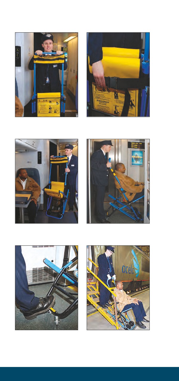
Instructions to Use Acela’s EVAC-CHAIR
Fig (1)
Fig (2)
Grip both sides of extension handle,
Slide headrest/torso restraint down to
then pull up until it locks in place.
mid-position and unbuckle safety lap
belt.
Fig (3)
Fig (4)
Pivot seat open, use foot to extend
Roll chair toward exit.
two inner wheels, assist passenger into
chair.
Fig (5)
Fig (6)
Align EVAC-CHAIR with top of
Roll chair onto folding stair. As chair
folding stair and use foot to retract
starts to descend, slide hands to grip
inner wheels.
top of handle. Press down on handle
for smoothest ride.
1-74
Passenger Train Emergency Preparedness
• Be supported while walking with a cane or
walker.
• Be lifted or carried away from the train.
6. Tunnel Information And Emergencies
Fires and other emergency situations occurring within a
tunnel are among the most difficult to cope with due
to the limited space and minimal lighting for fire and
emergency personnel. Due to the variety of hazards
involved, local fire and emergency authorities must
establish a direct line of communication between
railroad authorities and the division’s top management
personnel to keep emergency forces appraised of
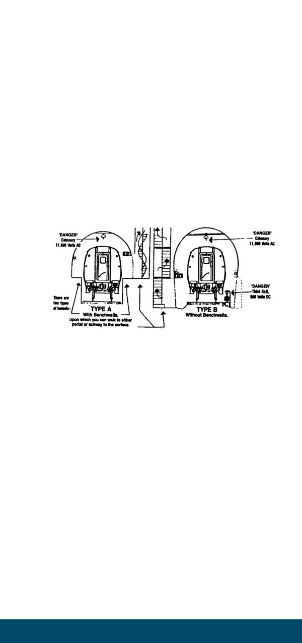
current conditions. (Refer to Figure 1-17)
Figure 1-17 - Tunnel Hazards
a)
Moving Trains in Tunnels
• In the event of a fire or emergency situation
on a train moving through a tunnel, every
effort must be made to expedite movement of
the train out of the tunnel.
• Train crews must promptly establish
communication with the engineer to discuss
appropriate action to keep the train moving.
• The train must not be stopped unless there is
reason to believe that derailment or personal
injury may otherwise result.
b) Evacuating Passengers from Tunnels
• Evacuating passengers from a train in a tunnel
should be a last resort in extreme emergencies.
• In the event of a severe fire, accident, or other
emergency occurring in a tunnel that endangers
the safety of passengers, the train crew and any
available emergency personnel must take
immediate action to stop all train movements
and escort the passengers from the train.
Service Standards Manual No. 6
1-75
• Passenger evacuation requires a safe place
of refuge, e.g., a station platform or vertical
exit way leading directly to open air.
• Passengers should evacuate the train to a
walkway on the side opposite, or a safe
distance away from, the power source.
• Train Dispatcher must be immediately
contacted that an evacuation is occurring.
c)
Electric Power Hazards in Tunnels
Electric (traction) power to operate electric
trains is transmitted by overhead catenary wires
(AC) or third rail (DC).
Employees working in catenary or third rail territory
must consider these systems live and lethal until it is
known the system is de-energized and properly
grounded.
Most third rail systems have cover boards
installed to prevent accidental contact. Amtrak
has such cover boards in the New York area.
Amtrak Safety Rules strictly prohibit employees
from standing, sitting on, walking on or touching
third rail cover boards.
Catenary systems supply electricity to electric
locomotive or MU cars through a pantograph
mounted on the roof of the locomotive or MU car.
Most AC electric locomotives, commuter agency
locomotives and MU cars operated on the NEC
are equipped with vacuum-type interrupt main
circuit breakers, which connect the pantograph to
the main transformer.
Pantograph(s) may be lowered using the
pantograph DOWN switch located in the engineer’s
control compartment. Some commuter agency
equipment has a pneumatically operated plunger
that, during certain fault conditions, acts to ground
and lower the pantograph simultaneously. In some
unusual cases, a pantograph pole may be required
to lower the pantograph(s). Pantograph poles are
located inside a tube mounted horizontally on the
side of a car or locomotive. Also, some electric
locomotives have a telescoping pantograph pole
mounted in the machine room.
1-76
Passenger Train Emergency Preparedness
If it is necessary to mount the roof of electric
equipment, the manual grounder, normally
labeled: "Danger High Voltage-Ground
Pantograph(s) Before Going on Roof," located
on the roof at the end of equipment or in the
machine room must be activated. Locomotive
pantographs are bussed together; therefore, if one
pantograph is against live overhead catenary wire
both pantographs are energized and dangerous.
When MU cars are interconnected (bussed), it is
necessary to lower all pantographs and manually
ground each car. The utmost caution must be taken
when applying manual grounding devices and must
only be done by or under the supervision of a Class
A or B employee.
Only Class A or B employees may go on the top
of electric equipment. All T & E employees are
Class C and must not get closer than 3 feet to the
catenary wire, unless proper protection is provided
by a Class A employee. (Refer to “Electrical
Operating Instructions” (AMT-2) for further
instructions.)
E.
Unusual Occurrence Reporting
Requirements
Conductors are responsible for thoroughly and
accurately completing an “Unusual Occurrence
Report” (NRPC 2673) when any of the following
qualifying events have occurred:
1.
Examples Of Qualifying Events To Be Reported
• Any grade crossing accident (public or private)
• Any derailment (yard, station, main line, etc.,
with one or more wheels on the ground).
• Any damage to on-track equipment (standing
or moving) that cannot be repaired by a train
crew en route but will be repaired before being
dispatched again at the home terminal.
• Any car, locomotive, or other on-track equipment,
incurring damage in a yard, terminal, and/or shop
that requires repair.
• Any car, locomotive, or other on-track equipment,
that is removed from service as a result of any
collision with damage.
Service Standards Manual No. 6
1-77
• Any physical damage to track, signals, catenary
and/or structures incurred while operating
on-track equipment on a main line, yard,
terminal, etc.
2.
Examples Of Events Not Qualifying For Reporting
• Air hose breaks
• Damage to 480 volt cables
• Damage to knuckles
• Bent grab irons
• Bent pilots
• Minor cracks in the wind-shield
• Minor debris strikes
• Minor vandalism
3.
Qualifying Event Reporting
• All qualifying events must be reported as soon
as possible to CNOC at (800) 424-0217 or ATS
734-2308.
• If in doubt as to whether the event is qualifying,
contact Central Reporting at ATS 777-3280.
• Fax the completed “Unusual Occurrence Report”
(NRPC 2673) to Amtrak’s Central Reporting Office
at (800) 888-2185 or ATS 777-2595 within 72 hours
of the occurrence.
• Submit the original “Unusual Occurrence Report”
(NRPC 2673) to your supervisor after faxing.
• Failure to comply with these requirements is a
violation of Federal Regulations 49 CFR - Part 225,
and could result in civil and criminal penalties.
(Refer to Figure 1-18)
1-78
Passenger Train Emergency Preparedness
Figure 1-18 - Unusual Occurrence Report (NRPC 2673)
Service Standards Manual No. 6
1-79
Introduction
This section covers threats to employees, passengers,
facilities, bridges, tunnels, stations and other assets of the
corporation. Included are the various threat levels and
information on bomb threats (receiving, response),
chemical, biological and radiological threats.
A. Bomb Threats and Unattended Items
Code 1000 - The Non-Specific Bomb Threat
Code 2000 - A Site-Specific Bomb Threat
Code 3000 - A Device or Suspected Device
Discovered
1.
Bomb Threat
For the purpose of this policy, the term “bomb threat”
shall include threats or notice that an incendiary or
explosive device has been or may be placed on
Amtrak’s right-of-way, on a train, in a station or
facility. Employees can assist the Amtrak Police by
becoming familiar with and following the guidelines
below.
2.
Receipt of a Bomb Threat
• Get another person to listen in on the conversation.
• Remain calm and keep the caller on the line as
long as possible.
• Record every word that is spoken.
• Ask for date, time of detonation, and the location .
• Listen for background noises, caller’s accent, tone
of voice, etc.
• Report all information immediately to Amtrak
Police at (800) 331-0008.
• Refer to the Bomb Threat Call Check List
(NRPC 1373) for guidance. (Refer to Figure 1-19)
Service Standards Manual No. 6
1-83
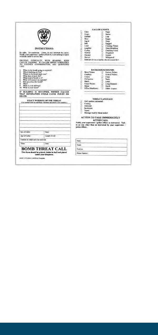
Figure 1-19 - Bomb Threat Call Check List (NRPC 1373)
3. Types of Bomb Threats
There are two basic types of bomb threats: the
non-specific and the specific threat. A series of codes
has been developed to help in responding to bomb
or other serious threats.
Code 1000 - The Non-Specific Threat
a) Definition
A non-specific threat is when a caller or letter
merely states there is a bomb on a train or in a
station, but gives no specific details. Examples
could include:
• A threat made against a train without a specific
train name, number, time or location.
• A threat involving a station, facility, tunnel or
bridge without a specific name or location of
the target.
b) Response
When a non-specific bomb threat has been made,
increase vigilance. Pay particular attention to
train compartments, station platforms and public
1-84
Terrorist Activity
areas for suspicious objects or packages. Report
any findings to the Amtrak Police Department at
(800) 331-0008.
Code 2000 - A Site-Specific Threat
a) Definition
A site-specific threat is when a caller or letter
provides a combination of specific information
about a bomb or explosive device. Examples
could include:
• A specific train number such as: train number 178.
• A specific station and or location in or about
the station such as: Baggage Room.
• A specific piece of luggage or baggage.
b) Response
Conduct a search of the potential target to identify
suspicious packages. Identify the owner(s) of
baggage and packages. If no device or suspected
device is discovered, scale back to a Code 1000
response fo the next 24 hours.
Code 3000 - A Device or Suspected Explosive
Device Discovered
a) Definition
A suspected explosive device has been discovered.
b) Response
When a suspected explosive device has been
discovered:
STOP!
MOVE AWAY!
DO NOT USE A RADIO OR CELL PHONE
NEAR THE SUSPECTED EXPLOSIVE DEVICE!
CONTACT AMTRAK POLICE IMMEDIATELY
at 800-331-0008 once clear from the suspected
explosive device. If unable to contact Amtrak Police
- contact Railroad Dispatcher.
At the direction of the Amtrak Police Department,
assist in the evacuation of the station, train, or facility
and/or the restricting of access to a particular area.
NO AMTRAK EMPLOYEE WILL TOUCH A
SUSPECTED EXPLOSIVE DEVICE.
The Amtrak Police and/or local police will coordinate.
Service Standards Manual No. 6
1-85

4.
Unattended Items Guide
a) If, during the course of your normal duties, you
discover an unattended item or an object that
appears out of place, please consider the following
(HOT Characteristics) when attempting to confirm
its status:
H - has the item been HIDDEN, or concealed?
O - is the item OBVIOUSLY suspicious? (i.e.,
looks like a bomb?)
T - is the item TYPICAL of what should be there?
b) Once you are satisfied that an item cannot be
accounted for through normal questioning,
consider the following factors:
LOW
LEVEL OF SUSPICION
HIGH
No
Any bomb threats?
Yes
No
Suspicious activity?
Yes
No
Has it been hidden?
Yes
No
Is the item unusual?
Yes
A “YES” response to any of the above questions results
in the item being considered suspicious.
CONTACT AMTRAK POLICE IMMEDIATELY
800-331-0008
DO NOT TOUCH IT
DO NOT OPEN IT
DO NOT TAMPER WITH IT
DO NOT MOVE IT
DO NOT COVER IT
REMEMBER to move away from the item before
using a radio or cell phone.
5.
Personal Safety Guide
a) If you think you are dealing with a bomb or
confirmed suspicious item, move yourself and
anyone nearby to an area that is:
• NOT in direct line of sight of the item.
• MORE than 300 feet away from a small item
(hand luggage, etc.).
• MORE than 600 feet away from a large item
or car.
1-86
Terrorist Activity
• MORE than 1200 feet away from a large vehicle
(load carrying vehicle).
• AWAY from glass and parked cars.
• AWAY from secondary hazards (i.e., gas,
electricity, etc.).
• BEHIND hard cover.
b) If on-board a train, move two (2) cars away from
the car containing the suspicious item and secure
all carbody end doors. Contact Amtrak Police at
(800) 331-0008. The following information will be
asked once you are in a safe location.
• WHAT it is (size, description, etc. - prepare
sketch if possible).
• WHERE it is (precise location, other hazards,
access route).
• WHY you think it is suspicious.
• WHO discovered it (or witnessed anything
suspicious).
B.
Chemical, Biological and Radiological
Threats
International terrorist incidents involving chemicals
such as nerve gas, the perceived potential for a
biological attack involving the disease smallpox, and
the increased use of radiation in weaponry worldwide,
attest to the belief of the United States government
that we are vulnerable to chemical, biological, and
radiological incidents. Transportation employees
should have a basic understanding of the difference
between these threats; some information on what
symptoms to look for; and immediate actions that
can be taken if one of these incidents occurs.
1.
Chemical Threats
Chemical agents come in the form of a solid, liquid
or gas. Some of the most familiar are Chlorine,
Cyanide and Sarin (used in the Tokyo subway attack).
a) Typical Observations:
• Rapid onset of medical symptoms (minutes to
hours).
• Easily observed signatures (i.e., colored
residue, dead foliage, pungent odor, dead insect
and/or animal life).
• Difficulty breathing or uncontrollable cough.
• Collapsing, nausea, seizures or blurred vision.
b) Actions to be Taken:
• Consider your personal safety first.
Service Standards Manual No. 6
1-87
• Notify Amtrak Police at (800) 331-0008 and
your supervisor immediately.
• If outside, evacuate upwind of the suspected area.
• If inside and the incident is inside, evacuate while
minimizing passage through the contaminated
area.
• Keep unused doors and windows closed.
• If inside and the incident is outside, stay inside.
• Turn off air conditioning, close/seal windows
and doors with plastic tape.
2.
Biological Threats
Biological agents are usually in liquid or dry form.
Cholera, Ebola and Anthrax (used in the U. S. Post
Office incidents) are examples of the most familiar
biological agents.
a)
Typical Observations:
• The onset of symptoms requires days to weeks,
no characteristic signatures.
• The actual incident would most likely be
identified following a threat, or after employees
or passengers have become ill.
• The affected area may be greater due to the
migration of contaminated individuals.
b) Actions to be Taken:
• Consider your personal safety first.
• Notify Amtrak Police at (800) 331-0008 and
your supervisor immediately.
• If outside, evacuate upwind of the suspected area.
• If inside and the incident is inside, evacuate.
while avoiding passage through the contaminated
area.
• Keep unused doors and windows closed.
• If inside and the incident is outside, stay inside.
• Turn off air conditioning, close/seal windows
and doors with plastic tape.
• If you suspect that you have become
contaminated, a soap and water shower
is the single most important action for
decontamination.
3.
Radiological Threats
Radiological materials are not recognizable by the
senses. They are colorless and odorless. Exposure
occurs when radioactive materials are introduced
1-88
Terrorist Activity
and contaminate an object, person or area.
a)
Typical Observations:
• The onset of symptoms requires days to weeks
and typically, there are no characteristic signs.
• In the case of a nuclear attack, an explosion
has taken place and in addition to the effects
of radiation, victims will show signs of burn or
heat-related injuries, and blast/ explosion related
injuries.
• A “dirty bomb” is a conventional explosive or
bomb containing radioactive material.
• The bomb is used as a means of spreading
radioactive materials.
• In the case of the detonation of a “dirty
bomb”, for those in the immediate vicinity, the
effects of the blast will overshadow the low
levels of radiation emitted.
b) Actions to be Taken:
• Consider your personal safety first.
• Notify Amtrak Police at (800) 331-0008 and
your supervisor immediately.
• Report the circumstances, and as much
information about the victims and/or the
scene as possible.
• If outside, evacuate upwind of the suspected area.
• In any suspected radiological incident, minimize
exposure by minimizing the time around the
suspected site.
• Maximize the distance between you and the site,
trying to place some shielding (i.e., buildings,
vehicles, train cars, land features such as a hill,
etc.) between yourself and the site.
• If inside and the incident is inside, evacuate
while avoiding the contaminated area.
• Keep unused doors and windows closed.
• If inside and the incident is outside, stay inside.
• Turn off air conditioning, close/seal windows
and doors with plastic tape.
C.
Host Railroad and Amtrak Joint
Security Procedures
Upon confirmation of a detonation of an explosive
device on or at one of the following specified areas
these procedures will be implemented:
• An Amtrak Train.
• An Amtrak Station.
Service Standards Manual No. 6
1-89
• Any Railroad Infrastructures (i.e. bridge, tunnel)
that passenger trains would operate over or
through.
• Any other U.S. rail operations. (i.e. freight,
commuter, subway)
These procedures can also be initiated if an imminent/
confirmed threat has been determined based on
credible information.
1)
Notification
a) If an event, specific to an explosive device (i.e.
detonation, discovery), occurs on-board an
Amtrak train, the train crew must; notify the
dispatcher in the following manner:
“Emergency, Emergency, Emergency.” Train
#_______, (describe event).
b) Upon notification, the Train Dispatcher will repeat
the emergency transmission to ensure all trains
are notified and then attempt to obtain further
information regarding the situation. The Train
Dispatcher must then ensure the appropriate
notifications are made to CNOC (800-424-0217)
and the Amtrak National Communications
Center (NCC) (800-331-0008).
2)
Response
Unless otherwise directed by the Dispatcher, passenger
trains hearing this emergency transmission must
bring their train to a safe stop clear of passenger
stations, tunnels and bridges. Trains stopped at a
passenger station, tunnel or bridge at the time of the
report must be dispatched clear of these structures
as soon as possible.
Once a train is stopped clear of the above structures
it must remain at that location until directed to
proceed by the Train Dispatcher.
a) When a train is stopped, crew members will not
initiate an evacuation unless instructed by or
coordinated with Train Dispatcher; or, if the
Conductor or any other crew member ascertains
that a clear and present danger exists regarding a
situation or threat on-board.
b) If any evacuation of a passenger train occurs, the
1-90
Terrorist Activity
Train Dispatcher must be notified immediately.
c) If directed to proceed by the Train Dispatcher, the
En Route Train Inspection procedures will apply
or if standing, the Standing Train Inspection
procedures will apply.
3)
En Route Train Inspection
Operating crews must take the following actions for
all en route passenger trains including any special
instructions from the Train Dispatcher:
a)
Make the following announcement: “On-Board
Incidents with a Police Response Announcement”
from “Service Standards for Train Service and
On-Board Service Employees ” Chapter 10 -
“On-Board Announcements & Signage” which
reads: Ladies and gentlemen, we will be delayed
[if not stopped, provide location where train
will stop] due to police activity. At this time, we
do not have an estimate for the length of this
delay. We ask you to remain in your seats and
please be prepared to identify your baggage
and provide photo identification if requested.
We apologize for any inconvenience and thank
you for your patience.
b) The Conductor must make a public address
announcement to all on-board employees that
their “immediate assistance” is required at this
time including the designated meeting location
on the train.
c)
The Conductor will conduct a Job Briefing with
all Train and On-Board Service employees to
review the Host Railroad and Amtrak Joint
Security Procedures and any instructions from
the Train Dispatcher.
d) The Conductors will be in charge and have
authority over all Train and On-Board Service
employees. All employees (i.e. Chef, LSAs, SAs,
TAs and ACs) must follow the Conductor’s
instructions; this is not discretionary.
e)
The Conductor will assume the responsibility for
simultaneously coordinating multiple inspections
of equipment as follows:
• The Train and On-Board Service employees
will perform an interior inspection checking all
restrooms, electrical lockers, overhead luggage
Service Standards Manual No. 6
1-91