Standard Specifications for Road, Bridge, and Municipal Construction 2020 (M 41-10) - page 52
 

  Главная      Manuals     Standard Specifications for Road, Bridge, and Municipal Construction 2020 (M 41-10)


Search            copyright infringement  


Content      ..     50      51      52      53     ..


Standard Specifications for Road, Bridge, and Municipal Construction 2020 (M 41-10) - page 52


Page 9-210 

Illumination, Signal, Electrical

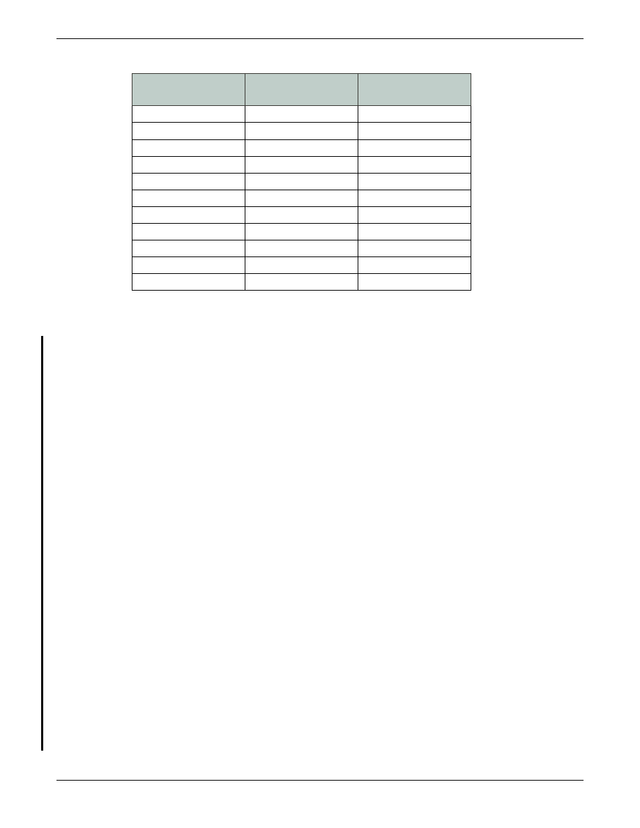
Legends shall correspond to the following code:

Conventional 

Lamp Wattage

Conventional 

Wattage Legend

Equivalent LED Legend

70

7

7E

100

10

10E

150

15

15E

175

17

17E

200

20

20E

250

25

25E

310

31

31E

400

40

40E

700

70

70E

750

75

75E

1,000

X1

X1E

9-29.10(1)  Conventional Roadway Luminaires

All conventional roadway luminaires shall meet 3G vibration requirements as described in 
ANSI C136.31.

All luminaires shall have housings fabricated from aluminum. The housing shall be painted 
flat gray, SAE AMS Standard 595 color chip No. 26280, unless otherwise specified in the 
Contract. Painted housings shall withstand a 1,000 hour salt spray test as specified in 
ASTM B117.

Each housing shall include a four bolt slip-fitter mount capable of accepting a nominal 
2” tenon and adjustable within +/- 5 degrees of the axis of the tenon. The clamping 
bracket(s) and the cap screws shall not bottom out on the housing bosses when adjusted 
within the +/- 5 degree range. No part of the slipfitter mounting brackets on the 
luminaires shall develop a permanent set in excess of 0.2 inch when the cap screws used 
for mounting are tightened to a torque of 32 foot-pounds. Each luminaire shall include 
leveling reference points for both transverse and longitudinal adjustment.

All luminaires shall include shorting caps when shipped. The caps shall be removed and 
provided to the Contracting Agency when an alternate control device is required to be 
installed in the photocell socket. House side shields shall be included when required by 
the Contract. Order codes shall be modified to the minimum extent necessary to include 
the option for house side shields.

9-29.10(1)A 

High Pressure Sodium (HPS) Conventional Roadway Luminaires

HPS conventional roadway luminaires shall meet the following requirements:
1.  General shape shall be “cobrahead” style, with flat glass lens and full cutoff optics.
2.  Light pattern distribution shall be IES Type III.

Illumination, Signal, Electrical 

9-29

3.  The reflector of all luminaires shall be of a snap-in design or secured with screws. 

The reflector shall be polished aluminum or prismatic borosilicate glass.

4.  Flat lenses shall be formed from heat resistant, high-impact, molded borosilicate or 

tempered glass.

5.  The lens shall be mounted in a doorframe assembly, which shall be hinged to 

the luminaire and secured in the closed position to the luminaire by means of 
an automatic latch. The lens and doorframe assembly, when closed, shall exert 
pressure against a gasket seat. The lens shall not allow any light output above 
90 degrees nadir. Gaskets shall be composed of material capable of withstanding the 
temperatures involved and shall be securely held in place.

6.  The ballast shall be mounted on a separate exterior door, which shall be hinged to 

the luminaire and secured in the closed position to the luminaire housing by means 
of an automatic type of latch (a combination hex/slot stainless steel screw fastener 
may supplement the automatic-type latch).

7.  Each luminaire shall be capable of accepting a 150, 200, 250, 310, or 400 watt lamp 

complete and associated ballast. Lamps shall mount horizontally.

9-29.10(1)B 

Light Emitting Diode (LED) Conventional Roadway Luminaires

LED Conventional Roadway Luminaires are divided into classes based on their equivalent 
High Pressure Sodium (HPS) luminaires. Current classes are 200W, 250W, 310W, 
and 400W. LED luminaires are required to be pre-approved in order to verify their 
photometric output. To be considered for pre-approval, LED luminaires must meet the 
requirements of this section.

LED luminaires shall include a removable access door, with tool-less entry, for access to 
electronic components and the terminal block. The access door shall be removable, but 
include positive retention such that it can hang freely without disconnecting from the 
luminaire housing. LED drivers may be mounted either to the interior of the luminaire 
housing or to the removable door itself.

LED drivers shall be removable for user replacement. All internal modular components 
shall be connected by means of mechanical plug and socket type quick disconnects. Wire 
nuts may not be used for any purpose. All external electrical connections to the luminaire 
shall be made through the terminal block.

LED luminaires shall include a 7-pin NEMA photocell receptacle. The LED driver(s) 
shall be dimmable from ten volts to zero volts. LED output shall have a Correlated 
Color Temperature (CCT) of 4000K nominal (4000-4300K) and a Color Rendering 
Index (CRI) of 70 or greater. LED output shall be a minimum of 85% at 75,000 hours at 
25 degrees Celsius.

LED luminaires shall be available for 120V, 240V, and 480V supply voltages. Voltages 
refer to the supply voltages to the luminaires present in the field. LED power usage shall 
not exceed the following maximum values for the applicable wattage class:

Page 9-212 

Illumination, Signal, Electrical

Class

Max. Wattage

200W

110W

250W

165W

310W

210W

400W

275W

Only one brand of LED conventional roadway luminaire may be used on a Contract. They 
do not necessarily have to be the same brand as any high-mast, underdeck, or wall-mount 
luminaires when those types of luminaires are specified in the Contract. LED luminaires 
shall include a standard 10 year manufacturer warranty.

The list of pre-approved LED Conventional Roadway Luminaires is available at  

www.wsdot.wa.gov/Design/Traffic/ledluminaires.htm

.

9-29.10(2) Vacant

9-29.10(3) Vacant

9-29.10(4)  Underdeck and Wall Mount Luminaires

Underdeck luminaires shall be weatherproof and corrosion resistant. Light distribution 
shall be as shown on the Contract. Each flush-mounted underdeck luminaire shall 
consist of a metal body, a prismatic refractor mounted in a doorframe, a prismatic glass 
or specular anodized aluminum reflector, a ballast, and a ceramic lamp socket and be 
supplied complete with all fasteners. The body shall have provisions for anchoring to 
concrete. The refractor shall be glass and shall be clearly identified as to “street side”. 
The doorframe assembly shall be hinged, gasketed and secured to the body.

Each wall-mounted luminaire shall consist of a metal body, a prismatic refractor mounted 
in a doorframe, an aluminum reflector with a specular anodized finish, an integral ballast 
and a ceramic lamp socket and supplied with all fasteners. The refractor shall be glass. 
A gasket shall be provided between the refractor and the body of the fixture.

All lamp sockets shall be positioned to locate the light center of the lamp within ½ inch of 
the light center location for which the luminaire is designed.

Ballasts for underdeck and wall luminaires shall conform to the provisions in 

Section 9-29.9

. Ballasts for underdeck and wall mount luminaires shall be installed in the 

luminaire housing.

9-29.10(5)  Sign Lighting Luminaires

Sign lighting luminaires shall be the Induction Bulb type.

9-29.10(5)A 

Sign Lighting Luminaires – Isolation Switch

The isolation switch shall be installed in a terminal cabinet per 

Section 9-29.25

with the 

exception that the cabinet shall be NEMA 3R and stainless steel. The terminal cabinet 
shall be installed in accordance with the 

Standard Plans

. The switch shall be either single 

Illumination, Signal, Electrical 

9-29

pole, single throw, or double pole single throw as necessary to open all conductors to the 
luminaires other than neutral and ground conductors. The switch shall contain 600-volt 
alternating current (VAC) terminal strips on the load side with solderless lugs as required 
for each load-carrying conductor plus four spare lugs per strip.

9-29.10(5)B 

Sign Lighting Fixtures-Induction

Sign lighting luminaires shall have a cast aluminum housing and door assembly with a 
polyester paint finish.

Each fixture shall consist of a housing, a reflector, refractor or lens, lamp socket, lamp, 
power coupler, a high frequency (HF) generator and a fuse block, door, front entry (the 
side facing the sign) suitable for ½-inch conduit and mounting holes for attaching to a 
fixture mounting plate. Any additional entries shall have suitable plugs. The sign lighting 
luminaire shall be supported by a lighting bracket assembly as detailed in the Plans. The 
door shall be hinged to the housing on the side of the fixture away from the sign panel 
and shall be provided with two captive devices. The door shall be provided with the 
means to allow the door to be locked in the open position 70 to 90 degree from the plane 
of the door opening. The juncture of the door and housing shall be gasketed to provide a 
rain tight and dust tight joint.

Refractors or lens shall be manufactured from heat resistant glass. The refractor or lens 
shall be shielded so that no light source is visible from the sign viewing approach. The 
shield shall be an integral part of the door assembly. When called for in the Plans, fixtures 
shall be provided with a wire guard to prevent damage to the refractor.

The ratio of the maximum to minimum illuminance level on a panel 10 feet high by 16 
feet wide shall not numerically exceed 9:1 approaching 1:1. In addition, the illuminance 
gradient shall not numerically exceed 2:1, illuminance gradient being defined as the ratio 
of the minimum illuminance of a square panel 1 foot on a side to that of any adjacent 
panel of the same size. This performance shall be obtained when the fixture is mounted 
1 foot below the bottom edge of the sign and 5 feet out from the sign face.

The average to minimum uniformity ratio for a panel as dimensioned above shall not 
numerically exceed 4:1. Average initial illuminance shall exceed 10 foot candles for an 
induction lamp of 85 watts as specified.

The system lifetime shall be rated at 60,000 hours with a failure rate of less than 
10 percent. The system shall be rated at a nominal wattage of 85 W, 120/240 or 
480V(ac). The power factor of the system shall be greater than 90 percent and the total 
harmonic distortion (THD) shall be less than 10 percent. The system shall be UL approved 
for wet locations and be FCC Class A listed.

The mounting assembly shall be either cast aluminum, hot-dip galvanized steel plate or 
steel plate that has been galvanized and finished with a polymeric coating system or the 
same finish that is used for the housing. The overall weight of the fixture shall not exceed 
44 pounds. The manufacturer’s brand name, trademark, model number, serial number and 
date of manufacture shall be located on the packaged assembly and on the outside and 
inside of the housing. 

Page 9-214 

Illumination, Signal, Electrical

Housing

The housing shall have a door designed to hold a refractor or lens. The housing door 
shall be designed to be opened without the use of tools. The housing and door shall have 
polyester paint finish of a gray color resembling unfinished fabricated aluminum.

Reflector

The reflector may be designed to be removed as a unit that includes the lamp and power 
coupler.

Lamp

Each fixture shall be furnished with an 85-W induction lamp. The interior lamp walls shall 
be fluorescent phosphor coated. Lamp light output shall be not less than 70 percent at 
60,000 hours. Lamps shall have a color-rendering index (CRI) of not less than 80. Lamps 
shall be rated at a color temperature of 4,000 K. Lamps shall be removable without the 
use of tools. 

Power Coupler

The power coupler shall consist of a construction base with antenna, heat sink and 
electrical connection cable. The power coupler shall be designed so that it can be 
removed with no more than common hand tools.

High Frequency Generator

High frequency (HF) generators shall provide reliable lamp starting and operation at 
ambient temperatures down to -15°F for the rated life of the lamp.

The generator output frequency shall be 2.65 MHz ± 10 percent. The generator radio 
frequency interference shall meet the requirements of Part 18 of the FCC. 

High frequency generators shall be designed for continuous operation at ambient air 
temperatures from -5°F to 80°F without reduction in generator life. High frequency 
generators shall have a design life of not less than 100,000 hours at 130°F.

A Manufacturer’s Certificate of Compliance, conforming to the provisions in 

Section 1-06.3

, and a copy of the high frequency generator test methods and results 

shall be submitted by the manufacturer with each lot of sign lighting fixtures. The 
certificate shall state that the high frequency generators meet, in every respect, the above 
requirements and the generator Specifications of the lamp manufacturer. High frequency 
generators shall also conform to the following:
1.  High frequency generators shall be capable of being easily replaced. All conductor 

terminals shall be identified as to the component terminal to which they connect.

2.  High frequency generators shall be mounted so as to use the portion of the sign 

lighting fixture upon which they are mounted as a heat sink.

Illumination, Signal, Electrical 

9-29

9-29.11 

Control Equipment

Illumination circuits shall be controlled by a combination of photoelectric controls and 
lighting contactors or mercury relays as noted in the Contract.

9-29.11(1)  Time Clock Controls

Time clocks, when specified in the Contract, shall be solid state and shall have a battery 
backup. The clock shall provide four functions and shall be enclosed within a dust tight 
mounting case. The unit shall be mounted on vibration dampened fittings.

The unit shall be push button programmable with 15 events per week, selectable by day 
of week and time of day to the nearest minute.

The clock shall be accurate to plus or minus 15 seconds per month through a humidity 
variation of 0 to 95 percent and a temperature variation of 0ºF to 150ºF. The clock shall 
be within plus or minus 10 seconds after 10 hours of battery backup operation. The 
backup battery shall operate for 24 hours minimum.

Contacts shall be rated at 5 amps tungsten load for up to 100,000 cycles. Each clock 
function shall operate a 120 VAC normally open and normally closed set of contacts.

9-29.11(2)  Photoelectric Controls

The photoelectric control shall be the twistlock type and the light sensitive element shall 
be a solid state photo diode. The control shall be designed to turn on at 3 foot-candles 
(32 lux) and turn off at 1.8 foot-candles (20 lux). The lighting control shall not drift by 
more than 1 percent over a 10-year period.

The output control relay shall have a 45-second time delay to prevent false turn-
off caused by momentary brightness. This output relay shall be rated 1,000 watts 
incandescent or 15 amps inductive load. The contacts shall be normally closed. The unit 
shall be designed to not continuously pulse the output relay if the photo control bypass 
switch is energized. 

The lighting control shall have a built in metal oxide varistor (MOV) rated 180 joules for 
lightning and transient protection. The control shall also have secondary zener diode and 
transient filter. The printed circuit board shall be coated to prevent corrosion. The normal 
operating voltage range will be 105 to 285 VAC.

9-29.12 

Electrical Splice Materials

Circuit splicing materials shall meet the following specifications.

9-29.12(1)  Illumination Circuit Splices

Underground illumination circuit splices shall be solderless crimped connections capable 
of securely joining the wires, both mechanically and electrically, as defined in 

Section 

8-20.3(8)

Aerial illumination splices shall be solderless crimp connectors or split bolt vice-

type connectors.

Page 9-216 

Illumination, Signal, Electrical

9-29.12(2)  Traffic Signal Splice Material

Induction loop splices and magnetometer splices shall use an uninsulated barrel-type 
crimped connector capable of being soldered.

9-29.12(3)  Splice Enclosures

9-29.12(3)A 

Heat Shrink Splice Enclosure

Heat shrink splice enclosures shall be medium or heavy wall cross-linked polyolefin, 
meeting the requirements of AMS-DTL-23053/15, with thermoplastic adhesive sealant. 
Heat shrink splices used for “wye” connections require rubber electrical mastic tape.

9-29.12(3)B Molded Splice Enclosure

Molded splice enclosures shall use epoxy resin in a clear rigid plastic mold. The material 
used shall be compatible with the insulation material of the insulated conductor or cable. 
The component materials of the resin insulation shall be packaged ready for convenient 
mixing without removing from the package.

9-29.12(4)  Re-Enterable Splice Enclosure

Re-enterable splice enclosures shall use either dielectric grease or a flexible resin 
contained in a two-piece plastic mold. The mold shall either snap together or use stainless 
steel hose clamps.

9-29.12(5)  Vinyl Electrical Tape for Splices

Vinyl electrical tape in splicing applications shall meet the requirements of MIL-I-24391C.

9-29.13 

Control Cabinet Assemblies

Control cabinet assemblies shall include all necessary equipment and auxiliary 
equipment for controlling the operation of traffic signals, programmable message signs, 
illumination systems, ramp meters, data stations, CCTV, and similar systems as required 
for the specific application. Traffic Signal Controller Cabinet Assemblies shall meet the 
requirements of the NEMA TS1 and TS2 specification or the California Department of 
Transportation “Transportation Electrical Equipment Specifications” (TEES) dated March 
12, 2009 as defined in this specification.

9-29.13(1)  Environmental, Performance, and Test Standards for Solid-State 

Traffic Controller Assemblies

The scope of this Specification includes the controller of solid-state design installed 
in a weatherproof controller cabinet. The controller assembly includes the cabinet, 
controller unit, load switches, signal conflict monitoring circuitry, accessory logic 
circuitry, AC line filters, vehicle detectors, coordination equipment and interface, and 
preemption equipment. NEMA control assemblies shall meet or exceed current NEMA TS 
1 Environmental Standards. Normal operation will be required while the control assembly 
is subjected to any combination of high and low environmental limits (such as low voltage 

Illumination, Signal, Electrical 

9-29

at high temperature with high repetition noise transients). All other control equipment 
shall meet the environmental requirements of California Department of Transportation 
“Transportation Electrical Equipment Specifications” (TEES) dated March 12, 2009.

The Contractor shall furnish to the Contracting Agency all guarantees and warranties 
furnished as a normal trade practice for all control equipment provided.

9-29.13(2) 

Traffic Signal Controller Assembly Testing

Each traffic signal controller assembly shall be tested as follows. The Contractor shall:
1.  Prior to shipping, arrange appointment for testing at the WSDOT Materials 

Laboratory.

2.  Assembly shall be defined as tightening all screws, nuts and bolts, verifying that 

all wiring is clear of moving parts and properly secured, installing all pluggables, 
connecting all cables and ensure that all Contract required documents are present, 
proper documentation is provided, and all equipment required by the Contract 
is installed.

3.  The Contractor shall demonstrate that all of the functions required by the Contract 

perform as intended. Demonstration shall include energizing the cabinet and 
verifying that all 8 phases, 4 pedestrian movements and 4 overlaps (as required by 
the Contract Provisions) operate per 

Section 9-29.13

. The Contractor shall place the 

controller in minimum recall with interval timing set at convenient value for testing 
purposes. Upon a satisfactory demonstration the controller assembly will then be 
accepted by WSDOT for testing.

4.  If the assembly and acceptance for testing is not complete within 7 calendar days of 

delivery, the Engineer may authorize the return of the assembly to the Contractor, 
with collect freight charges to the Contractor.

5.  WSDOT will test each traffic signal control assembly in accordance with the 

following test methods, WSDOT 

T 421

T 422

T 423

T 424

T 425

T 427

, and 

T 428

6.  If the traffic signal control assembly passes all testing, the Contractor will be notified 

where the assembly is to be picked-up for delivery to the project. The Contractor 
shall pick-up the assembly within 7 calendar days of notification.

7.  If the traffic signal control assembly fails testing, the Contractor has 7 calendar days 

to repair or replace any components that fail during the testing process at no cost 
to the Contracting Agency. All repairs shall be completed during normal business 
hours for the State Materials Lab. A failure shall be defined as a component that 
no longer functions as intended under the conditions required or does not meet 
the requirements of the Contract and is at the sole discretion of WSDOT. Once all 
repairs and replacement of components is complete WSDOT will retest the traffic 
controller as specified in step 6 and all costs for retesting will be deducted from 
monies due or that may become due the Contractor.

Page 9-218 

Illumination, Signal, Electrical

9-29.13(3)  Traffic Signal Controller

The traffic signal controller shall conform to the Contract requirements and the applicable 
Specifications as listed below: All solid-state electronic traffic-actuated controllers and 
their supplemental devices shall employ digital timing methods.
1.  NEMA control and all auxiliary equipment shall conform to current NEMA TS1 or 

TS2 Specification. Every pin of every connecting plug shall be utilized as described 
within the NEMA requirement, except that those pins identified as “spare” or “future” 
shall remain unused.

2.  Type 170E controllers shall conform to the TEES. The 170E controller shall be 

provided with a program card, one blank ROM chip, and two 64K non-volatile 
memory chips.

3.  Type 170E/HC-11 controllers shall conform to the current Oregon Department of 

Transportation Specification for model 170E/HC-11 controller. The 170E controller 
with the HC11 chip shall be compatible with the software specified in the Contract. 
The controller shall be provided with one ROM chip and one 64K non-volatile 
memory chip.

4.  Type 2070 controllers shall conform to the TEES. The standard 2070 controller shall 

consist of the following:

2070
2070-5 VME cage
2070-1E CPU Card
2070-3B Front Panel
2070-4 Power Supply
2070-2A Field I/O

X
2070E
2070-1E CPU Card
2070-3B Front Panel
2070-4 Power Supply
2070-2A Field I/O

X
2070N1
2070-1E CPU Card
2070-3B Front Panel
2070-4 Power Supply
2070-2B Field I/O
2070-8 Interface

9-29.13(4)  Traffic-Signal Controller Software

All traffic signal controllers shall operate with software specified in the contract.

Traffic-actuated controllers shall be electronic devices which, when connected to traffic 
detectors or other means of actuation, or both, shall operate the electrical traffic signal 
system at one or more intersections.

If the complete traffic controller defined in the Special Provision requires NTCIP 
compliance the following are the minimum requirements for NTCIP operation.

Communication

The traffic controller hardware and software shall communicate with the central 
computer in a polled multi-drop operation. In the polled multi-drop operation, 
several traffic controllers shall share the same communication channel, with each 
controller assigned a unique ID number. Controller ID numbers shall conform to 
the NTCIP requirements for address numbers. A traffic controller shall only reply 

Illumination, Signal, Electrical 

9-29

to messages labeled with its ID. In polled multi-drop mode, traffic controllers never 
initiate communication, but merely transmit their responses to messages from the 
central computer.
A laptop computer connected to the traffic controller’s local communication port 
shall have the same control and diagnostic capabilities as the central computer. 
However, local laptop control capability shall be limited to that traffic controller.

NTCIP Requirements

The traffic controller software shall comply with the National Transportation 
Communications for ITS Protocol (NTCIP) documents and all related errata sheets 
published before July 1, 1999 and as referenced herein.
The traffic controller software shall support the following standards:
1.  NTCIP 1101, Simple Transportation Management Framework (STMF), 

Conformance Level 1 (Simple Network Management Protocol (SNMP))

2.  NTCIP 2001, Class B Profile. All serial ports on the device shall support 

communications according to these standards.

3.  NTCIP 2101, SP-PMPP/RS232 Point-to-Multi-Point Protocol (PMPP)
4.  NTCIP 2201, NTCIP TP-Null Transport Profile Null (TP-NULL)
The traffic controller software shall implement all mandatory objects of all mandatory 
conformance groups as defined in NTCIP 1201, Global Object Definitions, and 
NTCIP 1202, Object Definitions for Actuated Traffic Signal Controller Units. Software 
shall implement the following conformance groups:
NTCIP 1202, Object Definitions for ASC

Conformance Group

Reference

Configuration

1201  2.2

Time Management

Time Base Event Schedule

Report

2.5

Phase

1202  2.2

Rings

2.8

Detector

2.3

Unit

2.4

Preempt

2.7

Time Base

2.6

Coordination

2.5

Channel

2.9

Overlaps

2.10

Page 9-220 

Illumination, Signal, Electrical

The software shall implement the following optional objects:
Objects required by these specifications shall support all values within its 
standardized range. The standardized range is defined by a size, range, or 
enumerated listing indicated in the object’s SYNTAX field and/or through descriptive 
text in the object’s description field. The following list indicates the modified object 
requirements for these objects.

Object Name

Object ID

Global Configuration

moduleType

Value 3

Database Management

dBCreateTransaction

All Values

dBErrorType

All values

Time Management

globslDaylightSavings

Values 2 and 3

Timebase Events 

Schedule

maxTimeBaseScheduleEntries

16

MaxDayPlans

15

MaxDayEvents

10

Report

maxEventLogCongifs

50

MventConfigMode

Values 2 thru 5

mventConfigAction

Values 2 and 3

MaxEventLogSize

255

MaxEventClasses

7

PMPP

maxGroupAddress

2

ASC Phase

maxPhases

8

pPhaseStartp

Values 2 thru 6

phaseOptions

All Values

maxPhaseGroups

1

Rings

maxRings

2

maxSequences

16

Detector

maxVehicleDetectors

64

vehicleDetectorOptions

All Values

maxPedestrianDetector

8

Unit

unitAutoPedestrianClear

All Values

unitControlStatus

All Values

unitFlashStatus

All Values

unitControl

All Values

maxAlarmGroups

1

Special Function

maxSpecialFunctionsOutputs

8

Illumination, Signal, Electrical 

9-29

Object Name

Object ID

Coordination

coordCorrectionMode

Values 2 thru 4

coordMaximumMode

Values 2 thru4

coordForceMode

Values 2 and 3

maxPatterns

48

patternTableType

Either 2,3 or 4

maxSplits

16

splitMode

Values 2 thru 7

localFreeStatus

Values 2 thru 11

Time Base 

maxTimebaseAscAction

48

Preempt

maxPreempts

4

preemptControl

All Values

preemptState

Values 2 thru 9

Overlaps

maxOverlaps

4

overlapType

Value 2 and 3

maxOverlapstatusGroup

1

Channels

maxChannels

16

channelControlGroup

Values 2 thru 4

channelFlash

Value 0,2,4,6,8,10,12 and 14

channelDim

Values 0 thru 15

maxChannelStatusGroup

2

TS 2 Port 1

maxPortAddresses

18

port1Table

Values 2 and 3

*Values in excess of the minimum requirement are considered to meet the specification.

Documentation

Software shall be supplied with all documentation on a CD. ASCII versions of the 
following Management Information Base (MIB) files in Abstract Syntax Notation 
1 (ASN.1) format shall be provided on CD-ROM:
1.  The official MIB Module referenced by the device functionality.
2.  A manufacturer-specific version of the official MIB Module with the non-

standardized range indicated in the SYNTAX field. The filename shall match the 
official MIB Module, with the extension “spc”.

3.  A MIB Module of all manufacturer-specific objects supported by the device 

with accurate and meaningful DESCRIPTION fields and the supported ranges 
indicated in the SYNTAX field.

Page 9-222 

Illumination, Signal, Electrical

9-29.13(5)  Flashing Operations

All traffic signals shall be equipped for flashing operation of signal displays. Controllers 
and cabinets shall be programmed for flashing red displays for all approaches. During 
flashing operation, all pedestrian circuits shall be de-energized.

Actuated traffic signal control mechanisms shall be capable of entry into flash operation 
and return to stop-and-go operation as follows:
1.  Terminal Strip Input (Remote Flash). When called as a function of a terminal strip 

input, the controller shall provide both sequenced entry into flash and sequenced 
return to normal operation consistent with the requirements of the latest edition of 
the 

Manual on Uniform Traffic Control Devices

.

2.  Police Panel Switch. When the flash-automatic switch located behind the police 

panel door is turned to the flash position, the signals shall immediately revert to 
flash; and, the controller shall have a stop time input applied. When the switch is 
placed on automatic, the controller shall immediately time an 6 second all red period 
then resume stop-and-go operations at the beginning of major street green.

3.  Controller Cabinet Switches. When the flash-automatic switch located inside the 

controller cabinet is placed in the flash position, the signals shall immediately revert 
to flash; however, the controller shall not have a stop time input applied. When 
the flash-automatic switch is placed in the automatic position, the controller shall 
immediately time a 6 second all red period, then resume stop-and-go operation at 
the beginning of the major green.

4.  Power Interruption. On “NEMA” controllers any power interruption longer than 

475 plus or minus 25 milliseconds, signals shall re-energize consistent with No. 2 
above to ensure an 6-second flash period prior to the start of major street green. A 
power interruption of less than 475 plus or minus 25 milliseconds shall not cause 
resequencing of the controller and the signal displays shall re-energize without 
change. Type 170 controllers shall re-energize consistent with No. 2 above after a 
power interruption of 1.75 plus or minus 0.25 seconds. The 6-second flash period 
will not be required. Any power interruption to a 2070 type controller shall result in a 
6 second flash period once power is restored.

5.  Conflict Monitor. Upon detecting a fault condition the conflict monitor shall 

immediately cause the signal to revert to flash and the controller to stop time. After 
the conflict monitor has been reset, the controller shall immediately take command 
of the signal displays at the beginning of major street green.

9-29.13(6)  Emergency Preemption

Immediately after a valid call has been received, the preemption equipment shall cause 
the controller to terminate the appropriate phases as necessary with the required 
clearance intervals and enter any programed subsequent preemption sequence. 
Preemption sequences shall be as noted in the Contract.

Illumination, Signal, Electrical 

9-29

9-29.13(7)  Wiring Diagrams

Schematic wiring diagrams of the controllers, cabinets and auxiliary equipment shall be 
submitted when the assemblies are delivered. The diagram shall show in detail all circuits 
and parts. The parts shall be identified by name or number in a manner readily interpreted. 
Two hard copies of the cabinet wiring diagram and component wiring diagrams shall be 
furnished with each cabinet and a pdf file of the cabinet wiring and component drawings. 
The schematic drawing shall consist of a single sheet, detailing all circuits and parts, not to 
exceed 52-inches by 72-inches. The cabinet wiring diagram shall indicate and identify all 
wire terminations, all plug connectors, and the locations of all equipment in the cabinet. 
Included in the diagram shall be an intersection sketch identifying all heads, detectors, 
and push buttons and a phase diagram.

9-29.13(8)  Generator Transfer Switch

When specified in the contract, a generator transfer switch shall be included. The 
Generator Transfer Switch shall be capable of switching power from a utility power source 
to an external generator power source.

The Transfer Switch enclosure shall be of identical materials and dimensions and 
installation methods as the Police Panel type enclosure specified in the first paragraph 
of Special Provision 9-29.13(10)D except that the enclosure door shall include a spring 
loaded construction core lock capable of accepting a Best 6-pin CX series core. The core 
lock shall be installed with a green construction core. Upon contract completion, two 
master keys for the construction core shall be delivered to the Engineer.

The enclosure shall include the following Transfer Switch equipment:
1.  One Nema L5-30P Flanged Inlet generator connector
2.  One Utility power indicator light
3.  One generator indicator light
4.  Two 30 amp, 120 volt, single pole, single phase, circuit breakers. One circuit breaker 

shall be labeled “Generator” and the other circuit breaker shall be labeled “Utility”. 
Both labels shall be engraved phenolic name plates.

5.  A mechanical lock out feature that prevents the Utility circuit breaker and the 

Generator circuit breaker from being in the ON position at the same time. The circuit 
breakers shall be capable of being independently switched.

6.  The conductors from the Generator Transfer Switch enclosure to the cabinet circuit 

breaker shall be enclosed in nylon mesh sleeve.

7.  The enclosure door shall be labeled with the letters “GTS”.

9-29.13(9) Vacant

Page 9-224 

Illumination, Signal, Electrical

9-29.13(10) NEMA, Type 170E, 2070 Controllers and Cabinets

9-29.13(10)A  Auxiliary Equipment for NEMA Controllers

The following auxiliary equipment shall be furnished and installed in each cabinet for 
NEMA traffic-actuated controllers:
1.  A solid-state Type 3 NEMA flasher with flash-transfer relay which will cut in the 

flasher and isolate the controller from light circuits. See

 Section 9-29.13(5) 

for 

operational requirements.

2.  Modular solid state relay load switches of sufficient number to provide for each 

vehicle phase (including future phases if shown in the Plans), each pedestrian phase 
and preemption sequence indicated in the Contract. Type P & R cabinets shall 
include a fully wired 16-position back panel. Solid-state load switches shall conform 
to NEMA standards except only optically isolated load switches will be allowed. Load 
switches shall include indicator lights on the input and output circuits. The controller 
cabinet shall have all cabinet wiring installed for eight vehicle phases, four pedestrian 
phases, four emergency pre-empts, four overlaps (OL A, B, C, D).

3.  A power panel with:

a.  A control-display breaker sized to provide 125 percent overload protection for 

all control equipment and signal displays, 20 ampere minimum.

b.  A 15 ampere accessory breaker wired parallel to the control display breaker. 

The breaker will carry accessory loads, including vent fan, cabinet light, plug 
receptacle, etc.

c.  A busbar isolated from ground and unfused for the neutral side of power supply.
d.  A radio interference suppresser installed at the input power point. Interference 

suppressers shall be of a design which will minimize interference in both 
broadcast and aircraft frequencies, and shall provide a minimum attenuation 
of 50 decibels over a frequency range of 200 kilohertz to 75 megahertz when 
used in connection with normal installations. The interference filters furnished 
shall be hermetically sealed in a substantial case filled with a suitable insulating 
compound. Terminals shall be nickel plated, 10-24 brass studs of sufficient 
external length to provide space to connect two 8 AWG wires, and shall be so 
mounted that they cannot be turned in the case.


Ungrounded terminals shall be insulated from each other and shall maintain a 
surface leakage distance of not less than ½-inch between any exposed current 
conductor and any other metallic parts with an insulation factor of 100-
200 megohms dependent on external circuit conditions.


Suppressers shall be designed for operations on 50 amperes, 125 volts, 
60 cycles, single wire circuits, and shall meet standards of the Underwriters’ 
Laboratories and the Radio Manufacturers Association.

e.  A Surge Protection Device connected to the controller power circuit for 

protection against voltage abnormalities of 1 cycle or less duration. The Surge 
Protection Device shall be a solid state high energy circuit containing no spark 

Illumination, Signal, Electrical 

9-29

gap, gas tube, or crow bar component. The device shall provide transient 
protection between neutral and ground, line and ground, as well as line and 
neutral. If the protection circuits fail, they shall fail to an open circuit condition. 
The minimum interrupting capacity shall be 10,000 Amps. The Voltage 
Protection Rating shall be 600 volts or less when subjected to an impulse of 
6,000 volts, 3,000 amp source impedance, 8.0/20 microsecond waveform as 
described in UL 1449. In addition, the device shall dissipate a 13,000 Amp or 
greater repeated single peak 8/20 microsecond current impulse, and withstand, 
without failure or permanent damage, one full cycle at 264 volts RMS. The 
device shall contain circuitry to prevent self-induced regenerative ringing. There 
shall be a failure warning indictor which shall illuminate a red light or extinguish 
a green light when the device has failed and is no longer operable.

f. 

Cabinet ground busbar independent (150K ohms minimum) of neutral.

4.  A police panel located behind the police panel door with a flash automatic 

switch and a control-display power line on-off switch. See 

Section 9-29.13(5)

 for 

operational requirements.

5.  An auxiliary control panel located inside the controller cabinet with a flash-automatic 

switch and a controller on-off switch. See 

Section 9-29.13(5)

 for operational 

requirements. A three wire 15 ampere plug receptacle with grounding contact and 
15 ampere ground fault interrupter shall also be provided on the panel.

6.  A conflict monitor conforming to NEMA standards. See 

Section 9-29.13(5)

 for 

operational requirements. The unit shall monitor conflicting signal indications at the 
field connection terminals. The unit shall be wired in a manner such that the signal 
will revert to flash if the conflict monitor is removed from service.


Supplemental loads not to exceed 10 watts per monitored circuit or other means, 
shall be provided to prevent conflict monitor actuation caused by dimming or 
lamp burn-out. Supplemental loads shall be installed on the control side of the 
field terminals. Conflict monitors shall include a minimum of one indicator light for 
each phase used. The monitoring capacity of the unit shall be compatible with the 
controller frame size. Conflict monitors shall include a program card.

7.  A “Detector Panel”, as specified in 

Section 9-29.13(10)B

, shall be installed. The panel 

shall be mounted on the inside of the front cabinet door. The detector panel shall be 
constructed as a single unit. Detector switches with separate operate, test, and off 
positions shall be provided for each field detector input circuit. A high intensity light 
emitting diode (LED) shall be provided for each switch. The lamp shall energize upon 
vehicle, pedestrian or test switch actuation. The test switch shall provide a spring 
loaded momentary contact that will place a call into the controller. When in the OFF 
position, respective detector circuits will be disconnected. In the operate position, 
each respective detector circuit shall operate normally. Switches shall be provided on 
the panel with labels and functions as follows:
a.  Display On — Detector indicator lights shall operate consistent with their 

respective switches.

b.  Display Off — Detector indicator lights shall be de-energized.


Content      ..     50      51      52      53     ..