ISO 32000-1 Document management — Portable document format — Part 1: PDF 1.7 - page 6
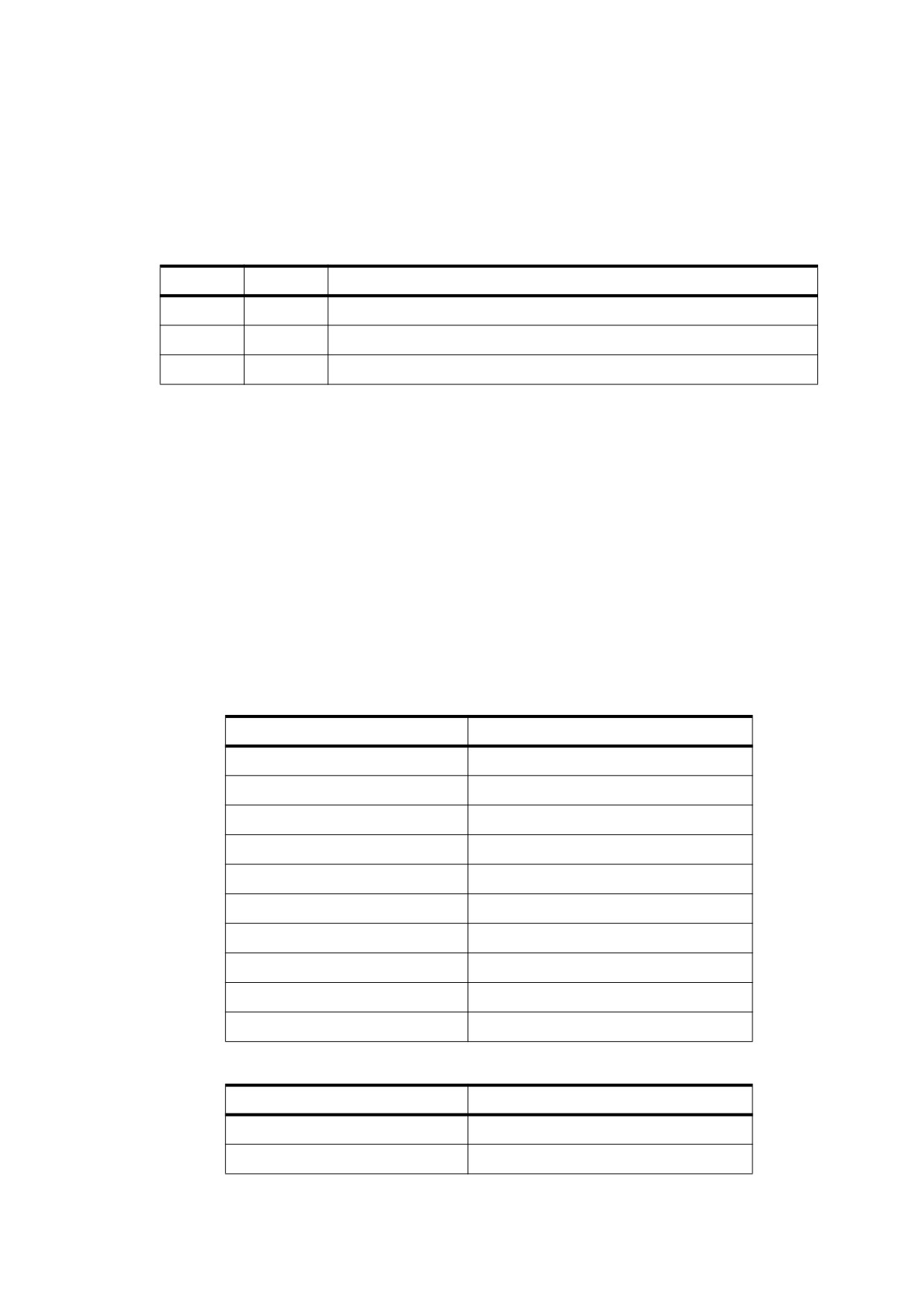
Table 83 shows the shading dictionary entries specific to this type of shading, in addition to those common to all
shading dictionaries (see Table 78) and stream dictionaries (see Table 5).
The data stream for a type 5 shading has the same format as for type 4, except that type 5 does not use edge
flags to define the geometry of the triangle mesh. The data for each vertex thus consists of the following values,
in the order shown:
x y c1… cn
where
x and y shall be the vertex’s horizontal and vertical coordinates
c
1… cn shall be its colour components
Table 83 - Additional Entries Specific to a Type 5 Shading Dictionary
Key
Type
Value
BitsPerCoordinate
integer
(Required) The number of bits used to represent each vertex
coordinate. The value shall be 1, 2, 4, 8, 12, 16, 24, or 32.
BitsPerComponent
integer
(Required) The number of bits used to represent each colour
component. The value shall be 1, 2, 4, 8, 12, or 16.
VerticesPerRow
integer
(Required) The number of vertices in each row of the lattice; the
value shall be greater than or equal to 2. The number of rows need
not be specified.
Decode
array
(Required) An array of numbers specifying how to map vertex
coordinates and colour components into the appropriate ranges of
values. The decoding method is similar to that used in image
dictionaries (see 8.9.5.2, "Decode Arrays"). The ranges shall be
specified as follows:
[xmin xmax ymin ymax c1,min c1,max
… cn,min cn,max ]
Only one pair of c values shall be specified if a Function entry is
present.
Function
function
(Optional) A 1-in, n-out function or an array of n 1-in, 1-out functions
(where n is the number of colour components in the shading
dictionary’s colour space). If this entry is present, the colour data for
each vertex shall be specified by a single parametric variable rather
than by n separate colour components. The designated function(s)
shall be called with each interpolated value of the parametric
variable to determine the actual colour at each point. Each input
value shall be forced into the range interval specified for the
corresponding colour component in the shading dictionary’s
Decode array. Each function’s domain shall be a superset of that
interval. If the value returned by the function for a given colour
component is out of range, it shall be adjusted to the nearest valid
value.
This entry shall not be used with an Indexed colour space.
All vertex coordinates are expressed in the shading’s target coordinate space. If the shading dictionary includes
a Function entry, only a single parametric value, t, shall be present for each vertex in place of the colour
components c1… cn .
The VerticesPerRow entry in the shading dictionary gives the number of vertices in each row of the lattice. All
of the vertices in a row shall be specified sequentially, followed by those for the next row. Given m rows of k
vertices each, the triangles of the mesh shall be constructed using the following triplets of vertices, as shown in
Figure 27:
193
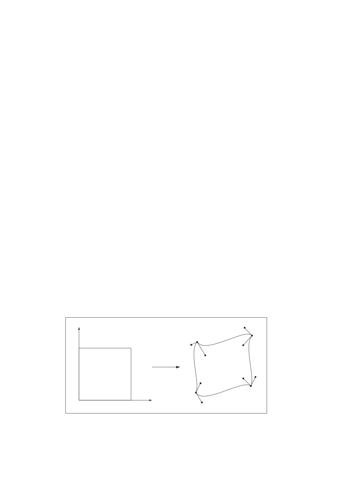
(Vi,j, Vi,j+1,
Vi+1j)
for 0 ≤ i ≤ m - 2, 0 ≤ j ≤ k - 2
,
(Vi,j+1,
Vi+1j,
Vi+1j+1)
,
,
See 8.7.4.5.5, "Type 4 Shadings (Free-Form Gouraud-Shaded Triangle Meshes)" for further details on the
format of the vertex data.
8.7.4.5.7 Type 6 Shadings (Coons Patch Meshes)
Type 6 shadings (Coons patch meshes) are constructed from one or more colour patches, each bounded by
four cubic Bézier curves. Degenerate Bézier curves are allowed and are useful for certain graphical effects. At
least one complete patch shall be specified.
A Coons patch generally has two independent aspects:
•
Colours are specified for each corner of the unit square, and bilinear interpolation is used to fill in colours
over the entire unit square (see the upper figure in Figure L.15 in Annex L).
•
Coordinates are mapped from the unit square into a four-sided patch whose sides are not necessarily
linear (see the lower figure in Figure L.15 in Annex L). The mapping is continuous: the corners of the unit
square map to corners of the patch and the sides of the unit square map to sides of the patch, as shown in
Figure 28.
The sides of the patch are given by four cubic Bézier curves, C1 , C2 , D1 , and D2 , defined over a pair of
parametric variables, u and v, that vary horizontally and vertically across the unit square. The four corners of
the Coons patch satisfy the following equations:
C1(0) = D1(0)
C1(1) = D2(0)
C2(0) = D1(1)
C2(1) = D2(1)
C2
D2
v
D1
C1
u
Figure 28 - Coordinate Mapping from a Unit Square to a Four-sided Coons Patch
Two surfaces can be described that are linear interpolations between the boundary curves. Along the u axis,
the surface SC is defined by
194

SC(u, v)
=
(1 - v)× C1(u)+ v× C2
(u
)
Along the v axis, the surface SD is given by
SD(u, v)
=
(1 - u)× D1(v)+ u× D2
(v
)
A third surface is the bilinear interpolation of the four corners:
SB(u, v)
=
(1-v)
×
[
(1-u)× C1
(0
) + u× C1
(1
)]
+
v
×
[
(1-u)× C2
(0
) + u× C2
(1
)]
The coordinate mapping for the shading is given by the surface S, defined as
S = SC+ SD– SB
This defines the geometry of each patch. A patch mesh is constructed from a sequence of one or more such
coloured patches.
Patches can sometimes appear to fold over on themselves—for example, if a boundary curve intersects itself.
As the value of parameter u or v increases in parameter space, the location of the corresponding pixels in
device space may change direction so that new pixels are mapped onto previous pixels already mapped. If
more than one point (u, v) in parameter space is mapped to the same point in device space, the point selected
shall be the one with the largest value of v. If multiple points have the same v, the one with the largest value of
u shall be selected. If one patch overlaps another, the patch that appears later in the data stream shall paint
over the earlier one.
NOTE
The patch is a control surface rather than a painting geometry. The outline of a projected square (that is, the
painted area) might not be the same as the patch boundary if, for example, the patch folds over on itself, as
shown in Figure 29.
Appearance
Painted area
Patch boundary
Figure 29 - Painted Area and Boundary of a Coons Patch
195

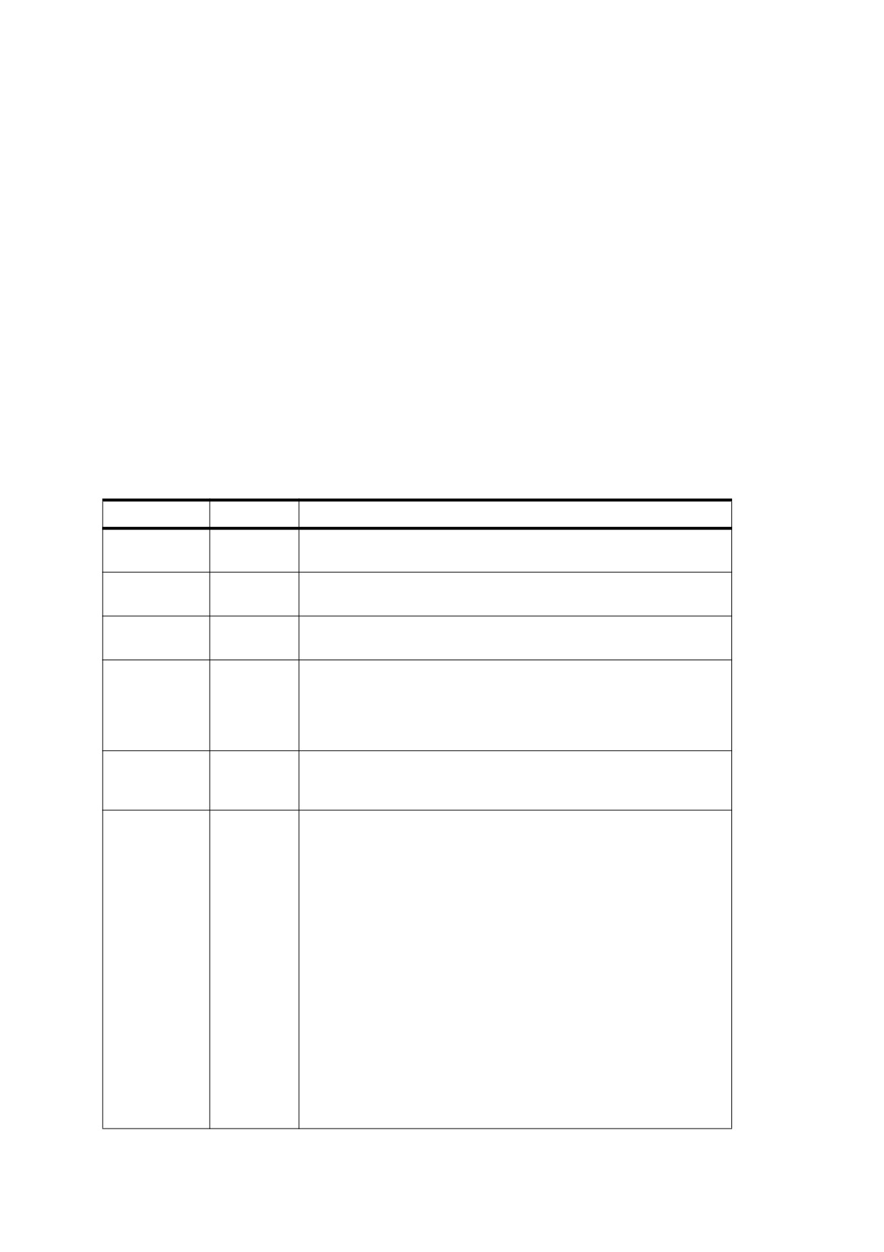
Table 84 shows the shading dictionary entries specific to this type of shading, in addition to those common to all
shading dictionaries (see Table 78) and stream dictionaries (see Table 5).
Table 84 - Additional Entries Specific to a Type 6 Shading Dictionary
Key
Type
Value
BitsPerCoordinate
integer
(Required) The number of bits used to represent each geometric
coordinate. The value shall be 1, 2, 4, 8, 12, 16, 24, or 32.
BitsPerComponent
integer
(Required) The number of bits used to represent each colour
component. The value shall be 1, 2, 4, 8, 12, or 16.
BitsPerFlag
integer
(Required) The number of bits used to represent the edge flag for
each patch (see below). The value shall be 2, 4, or 8, but only the
least significant 2 bits in each flag value shall be used. Valid values
for the edge flag shall be 0, 1, 2, and 3.
Decode
array
(Required) An array of numbers specifying how to map coordinates
and colour components into the appropriate ranges of values. The
decoding method is similar to that used in image dictionaries (see
8.9.5.2, "Decode Arrays"). The ranges shall be specified as follows:
[xmin xmax ymin ymax c1,min c1,max
… cn,min cn,max ]
Only one pair of c values shall be specified if a Function entry is
present.
Function
function
(Optional) A 1-in, n-out function or an array of n 1-in, 1-out functions
(where n is the number of colour components in the shading
dictionary’s colour space). If this entry is present, the colour data for
each vertex shall be specified by a single parametric variable rather
than by n separate colour components. The designated function(s)
shall be called with each interpolated value of the parametric
variable to determine the actual colour at each point. Each input
value shall be forced into the range interval specified for the
corresponding colour component in the shading dictionary’s
Decode array. Each function’s domain shall be a superset of that
interval. If the value returned by the function for a given colour
component is out of range, it shall be adjusted to the nearest valid
value.
This entry shall not be used with an Indexed colour space.
The data stream provides a sequence of Bézier control points and colour values that define the shape and
colours of each patch. All of a patch’s control points are given first, followed by the colour values for its corners.
This differs from a triangle mesh (shading types 4 and 5), in which the coordinates and colour of each vertex
are given together. All control point coordinates are expressed in the shading’s target coordinate space. See
8.7.4.5.5, "Type 4 Shadings (Free-Form Gouraud-Shaded Triangle Meshes)" for further details on the format of
the data.
As in free-form triangle meshes (type 4), each patch has an edge flag that indicates which edge, if any, it
shares with the previous patch. An edge flag of 0 begins a new patch, unconnected to any other. This shall be
followed by 12 pairs of coordinates, x1 y1 x2 y2 … x12 y12 , which specify the Bézier control points that define
the four boundary curves. Figure 30 shows how these control points correspond to the cubic Bézier curves C1 ,
C2 , D1 , and D2 identified in Figure 28. Colour values shall be given for the four corners of the patch, in the
same order as the control points corresponding to the corners. Thus, c1 is the colour at coordinates (x1 , y1 ), c2
at (x4 , y4 ), c3 at (x7 , y7 ), and c4 at (x10 , y10 ), as shown in the figure.
196
Use this side when next f = 1.
5
c
3
C2
c2
7
4
6
3
8
This side already attached
to previous patch. Start a
D1
D2
Use this side when next f = 2.
new patch when next f = 0.
9
12
2
10
1
c4
c1
C
1
11
Use this side when next f = 3.
Figure 30 - Colour Values and Edge Flags in Coons Patch Meshes
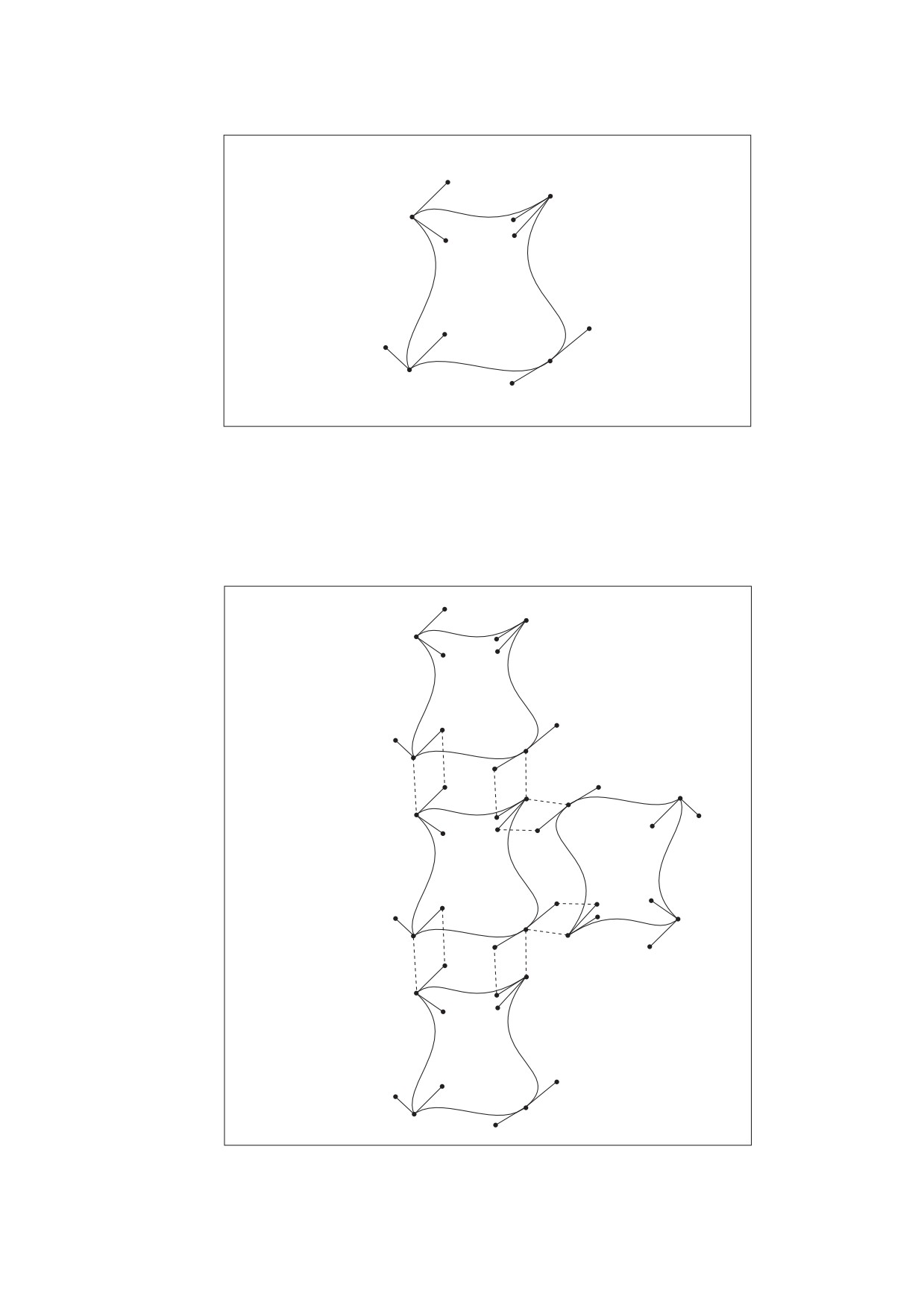
Figure 30 also shows how nonzero values of the edge flag (f = 1, 2, or 3) connect a new patch to one of the
edges of the previous patch. In this case, some of the previous patch’s control points serve implicitly as control
points for the new patch as well (see Figure 31), and therefore shall not be explicitly repeated in the data
stream. Table 85 summarizes the required data values for various values of the edge flag.
Patch B
fB = 1
2
4
1
c2
c1
3
5
c3
c1
c2
4
7
1
6
3
8
2
Patch B
When fB = 0, start a new patch.
fB = 2
Patch A
12
9
3
2
10
1
4
c4
c1
c2
11
3
c1
c2
4
1
2
Patch B
fB = 3
Figure 31 - Edge Connections in a Coons Patch Mesh
197

If the shading dictionary contains a Function entry, the colour data for each corner of a patch shall be specified
by a single parametric value t rather than by n separate colour components c1… cn . All linear interpolation
within the mesh shall be done using the t values. After interpolation, the results shall be passed to the
function(s) specified in the Function entry to determine the colour at each point.
Table 85 - Data Values in a Coons Patch Mesh
Edge Flag
Next Set of Data Values
f = 0
x
y1 x2 y2 x3 y3 x4 y4 x5 y5 x6 y6
1
x
y7 x8 y8 x9 y9 x10 y10 x11 y11 x12 y12
7
c
c2 c3 c4
1
New patch; no implicit values
f = 1
x
y5 x6 y6 x7 y7 x8 y8 x9 y9 x10 y10 x11 y11 x12 y12
5
c
c4
3
Implicit values:
(x1 , y1 ) = (x4 , y4 ) previous
c1 = c2 previous
(x2 , y2 ) = (x5 , y5 ) previous
c2 = c3 previous
(x3 , y3 ) = (x6 , y6 ) previous
(x4 , y4 ) = (x7 , y7 ) previous
f = 2
x
y5 x6 y6 x7 y7 x8 y8 x9 y9 x10 y10 x11 y11 x12 y12
5
c
c4
3
Implicit values:
(x1 , y1 ) = (x7 , y7 ) previous
c1 = c3 previous
(x2 , y2 ) = (x8 , y8 ) previous
c2 = c4 previous
(x3 , y3 ) = (x9 , y9 ) previous
(x4 , y4 ) = (x10 , y10 ) previous
f = 3
x
y5 x6 y6 x7 y7 x8 y8 x9 y9 x10 y10 x11 y11 x12 y12
5
c
c4
3
Implicit values:
(x1 , y1 ) = (x10 , y10 ) previous
c1 = c4 previous
(x2 , y2 ) = (x11 , y11 ) previous
c2 = c1 previous
(x3 , y3 ) = (x12 , y12 ) previous
(x4 , y4 ) = (x1 , y1 ) previous
8.7.4.5.8
Type 7 Shadings (Tensor-Product Patch Meshes)
Type 7 shadings (tensor-product patch meshes) are identical to type 6, except that they are based on a bicubic
tensor-product patch defined by 16 control points instead of the 12 control points that define a Coons patch.
The shading dictionaries representing the two patch types differ only in the value of the ShadingType entry and
in the number of control points specified for each patch in the data stream.
NOTE
Although the Coons patch is more concise and easier to use, the tensor-product patch affords greater control
over colour mapping.
198

Like the Coons patch mapping, the tensor-product patch mapping is controlled by the location and shape of
four cubic Bézier curves marking the boundaries of the patch. However, the tensor-product patch has four
additional, “internal” control points to adjust the mapping. The 16 control points can be arranged in a 4-by-4
array indexed by row and column, as follows (see Figure 32):
p03
p13
p23
p33
p02
p12
p22
p32
p01
p11
p21
p31
p00
p10
p20
p30
p13
p03
p33
p23
p32
p02
p12
p22
p11
p21
p01
p10
p31
p
p00
30
p20
Figure 32 - Control Points in a Tensor-product Patch
As in a Coons patch mesh, the geometry of the tensor-product patch is described by a surface defined over a
pair of parametric variables, u and v, which vary horizontally and vertically across the unit square. The surface
is defined by the equation
3
3
S(u, v)
=
pij × Bi(u)× Bj(v)
∑
∑
i= 0
j =0
where pij is the control point in column i and row j of the tensor, and Bi and Bj are the Bernstein polynomials
B0(t)
=
(1-t)3
B1(t)
=
3t
×
(1-t)2
B2(t)
=
3t2
×(1-t)
B3(t) = t3
Since each point pij is actually a pair of coordinates (xij , yij ), the surface can also be expressed as
199
3
3
x(u, v)
=
xij × Bi (u)× Bj (v)
∑
∑
i =0
j= 0
3
3
y(u, v)
=
yij × Bi (u)× Bj (v)
∑
∑
i =0
j= 0
The geometry of the tensor-product patch can be visualized in terms of a cubic Bézier curve moving from the
bottom boundary of the patch to the top. At the bottom and top, the control points of this curve coincide with
those of the patch’s bottom (p00… p30 ) and top (p03… p33 ) boundary curves, respectively. As the curve moves
from the bottom edge of the patch to the top, each of its four control points follows a trajectory that is in turn a
cubic Bézier curve defined by the four control points in the corresponding column of the array. That is, the
starting point of the moving curve follows the trajectory defined by control points p00… p03 , the trajectory of the
ending point is defined by points p30… p33 , and those of the two intermediate control points by p10… p13 and
p20… p23 . Equivalently, the patch can be considered to be traced by a cubic Bézier curve moving from the left
edge to the right, with its control points following the trajectories defined by the rows of the coordinate array
instead of the columns.
The Coons patch (type 6) is actually a special case of the tensor-product patch (type 7) in which the four
internal control points (p11 , p12 , p21 , p22 ) are implicitly defined by the boundary curves. The values of the
internal control points are given by these equations:
p11
=
1⁄9
×
[
-4
×
p00
+
6
×
(
p01
+
p10
)
–
2
×
(
p03
+
p30
)
+
3
×
(
p31
+
p13
)
–
1
×
p33
]
p12
=
1⁄9
×
[
-4
×
p03
+
6
×
(
p02
+
p13
)
–
2
×
(
p00
+
p33
)
+
3
×
(
p32
+
p10
)
–
1×p30
]
p21
=
1⁄9
×
[
-4
×
p30
+
6
×
(
p31
+
p20
)
–
2
×
(
p33
+
p00
)
+
3
×
(
p01
+
p23
)
–
1
×
p03
]
p22
=
1⁄9
×
[
-4
×
p33
+
6
×
(
p32
+
p23
)
–
2
×
(
p30
+
p03
)
+
3
×
(
p02
+
p20
)
–
1
×
p00
]
In the more general tensor-product patch, the values of these four points are unrestricted.
The coordinates of the control points in a tensor-product patch shall be specified in the shading’s data stream in
the following order:
4
5
6
7
3
14
15
8
2
13
16
9
1
12
11
10
All control point coordinates shall be expressed in the shading’s target coordinate space. These shall be
followed by the colour values for the four corners of the patch, in the same order as the corners themselves. If
the patch’s edge flag f is 0, all 16 control points and four corner colours shall be explicitly specified in the data
stream. If f is 1, 2, or 3, the control points and colours for the patch’s shared edge are implicitly understood to
be the same as those along the specified edge of the previous patch and shall not be repeated in the data
stream. Table 86 summarizes the data values for various values of the edge flag f, expressed in terms of the
200

row and column indices used in Figure 32. See 8.7.4.5.5, "Type 4 Shadings (Free-Form Gouraud-Shaded
Triangle Meshes)" for further details on the format of the data.
Table 86 - Data values in a tensor-product patch mesh
Edge Flag
Next Set of Data Values
f = 0
x00 y00 x01 y01 x02 y02 x03 y03 x13 y13 x23 y23 x33 y33 x32 y32
x31 y31 x30 y30 x20 y20 x10 y10 x11 y11 x12 y12 x22 y22 x
y
21
21
c00 c03 c33 c30
New patch; no implicit values
f = 1
x13 y13 x23 y23 x33 y33 x32 y32 x31 y31 x30 y30
x20 y20 x10 y10 x11 y11 x12 y12 x22 y22 x21 y21
c33 c30
Implicit values:
(x00 , y00 ) = (x03 , y03 ) previous
c00 = c03 previous
(x01 , y01 ) = (x13 , y13 ) previous
c03 = c33 previous
(x02 , y02 ) = (x23 , y23 ) previous
(x03 , y03 ) = (x33 , y33 ) previous
f = 2
x13 y13 x23 y23 x33 y33 x32 y32 x31 y31 x30 y30
x20 y20 x10 y10 x11 y11 x12 y12 x22 y22 x21 y21
c33 c30
Implicit values:
(x00 , y00 ) = (x33 , y33 ) previous
c00 = c33 previous
(x01 , y01 ) = (x32 , y32 ) previous
c03 = c30 previous
(x02 , y02 ) = (x31 , y31 ) previous
(x03 , y03 ) = (x30 , y30 ) previous
f = 3
x13 y13 x23 y23 x33 y33 x32 y32 x31 y31 x30 y30
x20 y20 x10 y10 x11 y11 x12 y12 x22 y22 x21 y21
c33 c30
Implicit values:
(x00 , y00 ) = (x30 , y30 ) previous
c00 = c30 previous
(x01 , y01 ) = (x20 , y20 ) previous
c03 = c00 previous
(x02 , y02 ) = (x10 , y10 ) previous
(x03 , y03 ) = (x00 , y00 ) previous
8.8
External Objects
8.8.1
General
An external object (commonly called an XObject) is a graphics object whose contents are defined by a self-
contained stream, separate from the content stream in which it is used. There are three types of external
objects:
•
An image XObject (8.9.5, "Image Dictionaries") represents a sampled visual image such as a photograph.
•
A form XObject (8.10, "Form XObjects") is a self-contained description of an arbitrary sequence of
graphics objects.
•
A PostScript XObject (8.8.2, "PostScript XObjects") contains a fragment of code expressed in the
PostScript page description language. PostScript XObjects should not be used.
201
Two further categories of external objects, group XObjects and reference XObjects (both PDF 1.4), are actually
specialized types of form XObjects with additional properties. See 8.10.3, "Group XObjects" and 8.10.4,
"Reference XObjects" for additional information.
Any XObject can be painted as part of another content stream by means of the Do operator (see Table 87).
This operator applies to any type of XObject—image, form, or PostScript. The syntax is the same in all cases,
although details of the operator’s behaviour differ depending on the type.
Table 87 - XObject Operator
Operands
Operator
Description
name
Do
Paint the specified XObject. The operand name shall appear as a key in
the XObject subdictionary of the current resource dictionary (see 7.8.3,
"Resource Dictionaries"). The associated value shall be a stream whose
Type entry, if present, is XObject. The effect of Do depends on the value
of the XObject’s Subtype entry, which may be Image (see 8.9.5, "Image
Dictionaries"), Form
(see 8.10, "Form XObjects"), or PS (see 8.8.2,
"PostScript XObjects").
8.8.2
PostScript XObjects
Beginning with PDF 1.1, a content stream may include PostScript language fragments. These fragments may
be used only when printing to a PostScript output device; they shall have no effect either when viewing the
document on-screen or when printing it to a non-PostScript device. In addition, conforming readers may not be
able to interpret the PostScript fragments. Hence, this capability should be used with extreme caution and only
if there is no other way to achieve the same result. Inappropriate use of PostScript XObjects can cause PDF
files to print incorrectly.
A PostScript XObject is an XObject stream whose Subtype entry has the value PS. A PostScript XObject
dictionary may contain the entries shown in Table 88 in addition to the usual entries common to all streams
(see Table 5).
Table 88 - Additional Entries Specific to a PostScript XObject Dictionary
Key
Type
Value
Type
name
(Optional) The type of PDF object that this dictionary describes; if present,
shall be XObject for a PostScript XObject.
Subtype
name
(Required) The type of XObject that this dictionary describes; shall be PS for
a PostScript XObject.
Alternatively, the value of this entry may be Form, with an additional
Subtype2 entry whose value shall be PS.
Level1
stream
(Optional) A stream whose contents shall be used in place of the PostScript
XObject’s stream when the target PostScript interpreter is known to support
only LanguageLevel 1.
If a PDF content stream is translated by a conforming reader into the PostScript language, any Do operation
that references a PostScript XObject may be replaced by the contents of the XObject stream itself. The stream
shall be copied without interpretation. The PostScript fragment may use Type 1 and TrueType fonts listed in the
Font subdictionary of the current resource dictionary (see 7.8.3, "Resource Dictionaries"), accessing them by
their BaseFont names using the PostScript findfont operator. The fragment shall not use other types of fonts
listed in the Font subdictionary. It should not reference the PostScript definitions corresponding to PDF
procedure sets (see 14.2, "Procedure Sets"), which are subject to change.
202
8.9
Images
8.9.1
General
PDF’s painting operators include general facilities for dealing with sampled images. A sampled image (or just
image for short) is a rectangular array of sample values, each representing a colour. The image may
approximate the appearance of some natural scene obtained through an input scanner or a video camera, or it
may be generated synthetically.
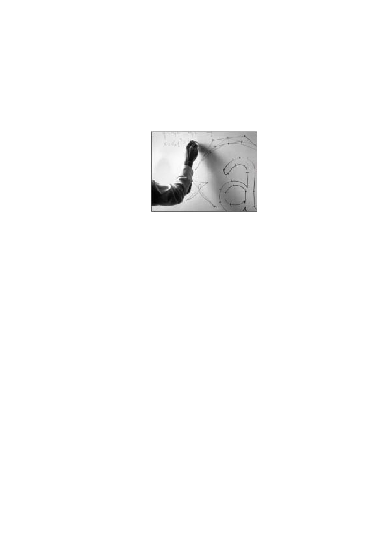
Figure 33 - Typical Sampled Image
NOTE 1
An image is defined by a sequence of samples obtained by scanning the image array in row or column order.
Each sample in the array consists of as many colour components as are needed for the colour space in which
they are specified—for example, one component for DeviceGray, three for DeviceRGB, four for
DeviceCMYK, or whatever number is required by a particular DeviceN space. Each component is a 1-, 2-, 4-,
8-, or (PDF 1.5) 16-bit integer, permitting the representation of 2, 4, 16, 256, or (PDF 1.5) 65536 distinct values
for each component. Other component sizes can be accommodated when a JPXDecode filter is used; see
7.4.9, "JPXDecode Filter".
NOTE 2
PDF provides two means for specifying images:
An image XObject (described in 8.9.5, "Image Dictionaries") is a stream object whose dictionary specifies
attributes of the image and whose data contains the image samples. Like all external objects, it is painted on
the page by invoking the Do operator in a content stream (see 8.8, "External Objects"). Image XObjects have
other uses as well, such as for alternate images (see 8.9.5.4, "Alternate Images"), image masks (8.9.6,
"Masked Images"), and thumbnail images (12.3.4, "Thumbnail Images").
An inline image is a small image that is completely defined—both attributes and data—directly inline within a
content stream. The kinds of images that can be represented in this way are limited; see 8.9.7, "Inline Images"
for details.
8.9.2
Image Parameters
The properties of an image—resolution, orientation, scanning order, and so forth—are entirely independent of
the characteristics of the raster output device on which the image is to be rendered. A conforming reader
usually renders images by a sampling technique that attempts to approximate the colour values of the source
as accurately as possible. The actual accuracy achieved depends on the resolution and other properties of the
output device.
To paint an image, four interrelated items shall be specified:
•
The format of the image: number of columns (width), number of rows (height), number of colour
components per sample, and number of bits per colour component
•
The sample data constituting the image’s visual content
203
•
The correspondence between coordinates in user space and those in the image’s own internal coordinate
space, defining the region of user space that will receive the image
•
The mapping from colour component values in the image data to component values in the image’s colour
space
All of these items shall be specified explicitly or implicitly by an image XObject or an inline image.
NOTE
For convenience, the following sub-clauses refer consistently to the object defining an image as an image
dictionary. Although this term properly refers only to the dictionary portion of the stream object representing an
image XObject, it should be understood to apply equally to the stream’s data portion or to the parameters and
data of an inline image.
8.9.3
Sample Representation
The source format for an image shall be described by four parameters:
•
The width of the image in samples
•
The height of the image in samples
•
The number of colour components per sample
•
The number of bits per colour component
The image dictionary shall specify the width, height, and number of bits per component explicitly. The number
of colour components shall be inferred from the colour space specified in the dictionary.
NOTE
For images using the JPXDecode filter (see 7.4.9, "JPXDecode Filter"), the number of bits per component is
determined from the image data and not specified in the image dictionary. The colour space may or may not be
specified in the dictionary.
Sample data shall be represented as a stream of bytes, interpreted as 8-bit unsigned integers in the range 0 to
255. The bytes constitute a continuous bit stream, with the high-order bit of each byte first. This bit stream, in
turn, is divided into units of n bits each, where n is the number of bits per component. Each unit encodes a
colour component value, given with high-order bit first; units of 16 bits shall be given with the most significant
byte first. Byte boundaries shall be ignored, except that each row of sample data shall begin on a byte
boundary. If the number of data bits per row is not a multiple of 8, the end of the row is padded with extra bits to
fill out the last byte. A conforming reader shall ignore these padding bits.
Each n-bit unit within the bit stream shall be interpreted as an unsigned integer in the range 0 to 2n- 1, with the
high-order bit first. The image dictionary’s Decode entry maps this integer to a colour component value,
equivalent to what could be used with colour operators such as sc or g. Colour components shall be
interleaved sample by sample; for example, in a three-component RGB image, the red, green, and blue
components for one sample are followed by the red, green, and blue components for the next.
If the image dictionary's ImageMask entry is false or absent, the colour samples in an image shall be
interpreted according to the colour space specified in the image dictionary (see 8.6, "Colour Spaces"), without
reference to the colour parameters in the graphics state. However, if the image dictionary’s ImageMask entry is
true, the sample data shall be interpreted as a stencil mask for applying the graphics state’s nonstroking colour
parameters (see 8.9.6.2, "Stencil Masking").
8.9.4
Image Coordinate System
Each image has its own internal coordinate system, or image space. The image occupies a rectangle in image
space w units wide and h units high, where w and h are the width and height of the image in samples. Each
sample occupies one square unit. The coordinate origin (0, 0) is at the upper-left corner of the image, with
coordinates ranging from 0 to w horizontally and 0 to h vertically.
204
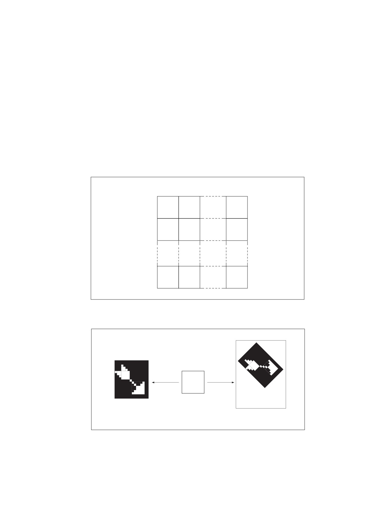
The image’s sample data is ordered by row, with the horizontal coordinate varying most rapidly. This is shown
in Figure 34, where the numbers inside the squares indicate the order of the samples, counting from 0. The
upper-left corner of the first sample is at coordinates (0, 0), the second at (1, 0), and so on through the last
sample of the first row, whose upper-left corner is at (w - 1, 0) and whose upper-right corner is at (w, 0). The
next samples after that are at coordinates (0, 1), (1, 1), and so on to the final sample of the image, whose
upper-left corner is at (w - 1, h - 1) and whose lower-right corner is at (w, h).
NOTE
The image coordinate system and scanning order imposed by PDF do not preclude using different conventions
in the actual image. Coordinate transformations can be used to map from other conventions to the PDF
convention.
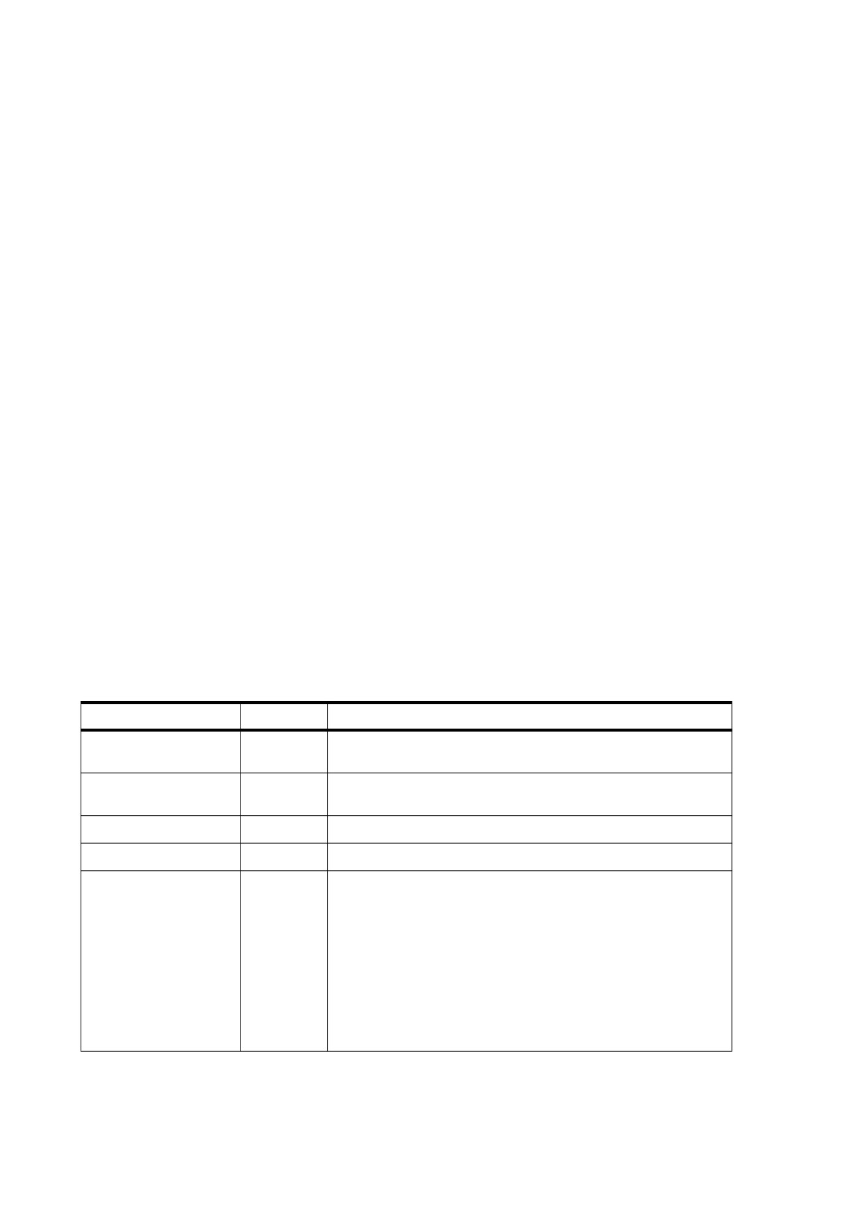
The correspondence between image space and user space is constant: the unit square of user space, bounded
by user coordinates (0, 0) and (1, 1), corresponds to the boundary of the image in image space (see Figure
35). Following the normal convention for user space, the coordinate (0, 0) is at the lower-left corner of this
square, corresponding to coordinates (0, h) in image space. The implicit transformation from image space to
user space, if specified explicitly, would be described by the matrix [ 1 ⁄ w 0 0 -1 ⁄ h 0 1 ].
0
1
2
w-1
w
0
0
1
w-1
1
w
w+1
2w-1
2
h-1
(h-1)w
(h-1)w+1
hw-1
h
Figure 34 - Source Image Coordinate System
0
w
0
(0, 1)
(1, 1)
CTM
h
(0, 0)
(1, 0)
Unit square
Source image
in user space
Current page
Figure 35 - Mapping the Source Image
An image can be placed on the output page in any position, orientation, and size by using the cm operator to
modify the current transformation matrix (CTM) so as to map the unit square of user space to the rectangle or
parallelogram in which the image shall be painted. Typically, this is done within a pair of q and Q operators to
205
isolate the effect of the transformation, which can include translation, rotation, reflection, and skew (see 8.3,
"Coordinate Systems").
EXAMPLE
If the XObject subdictionary of the current resource dictionary defines the name Image1 to denote an
image XObject, the code shown in this example paints the image in a rectangle whose lower-left corner is
at coordinates (100, 200), that is rotated 45 degrees counter clockwise, and that is 150 units wide and 80
units high.
q
% Save graphics state
1 0 0 1 100 200 cm
% Translate
0. 7071 0. 7071 -0. 7071 0. 7071 0 0 cm
% Rotate
150 0 0 80 0 0 cm
% Scale
/Image1 Do
% Paint image
Q
% Restore graphics state
As discussed in 8.3.4, "Transformation Matrices", these three transformations could be combined into
one. Of course, if the aspect ratio (width to height) of the original image in this example is different from
150:80, the result will be distorted.
8.9.5
Image Dictionaries
8.9.5.1
General
An image dictionary—that is, the dictionary portion of a stream representing an image XObject—may contain
the entries listed in Table 89 in addition to the usual entries common to all streams (see Table 5). There are
many relationships among these entries, and the current colour space may limit the choices for some of them.
Attempting to use an image dictionary whose entries are inconsistent with each other or with the current colour
space shall cause an error.
The entries described here are appropriate for a base image—one that is invoked directly with the Do operator.
Some of the entries should not be used for images used in other ways, such as for alternate images (see
8.9.5.4, "Alternate Images"), image masks (see 8.9.6, "Masked Images"), or thumbnail images (see 12.3.4,
"Thumbnail Images"). Except as noted, such irrelevant entries are simply ignored by a conforming reader
Table 89 - Additional Entries Specific to an Image Dictionary
Key
Type
Value
Type
name
(Optional) The type of PDF object that this dictionary describes; if
present, shall be XObject for an image XObject.
Subtype
name
(Required) The type of XObject that this dictionary describes; shall
be Image for an image XObject.
Width
integer
(Required) The width of the image, in samples.
Height
integer
(Required) The height of the image, in samples.
ColorSpace
name or
(Required for images, except those that use the JPXDecode filter;
array
not allowed forbidden for image masks) The colour space in which
image samples shall be specified; it can be any type of colour
space except Pattern.
If the image uses the JPXDecode filter, this entry may be present:
•
If ColorSpace is present, any colour space specifications in
the JPEG2000 data shall be ignored.
•
If ColorSpace is absent, the colour space specifications in the
JPEG2000 data shall be used. The Decode array shall also be
ignored unless ImageMask is true.
206
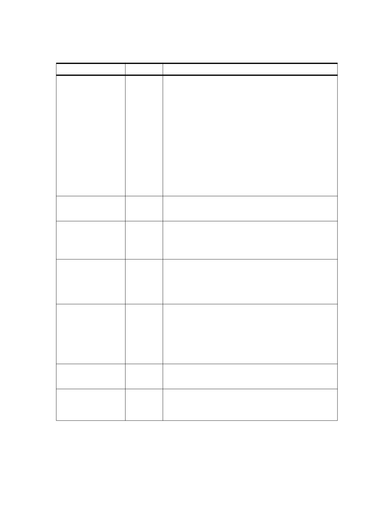
Table 89 - Additional Entries Specific to an Image Dictionary (continued)
Key
Type
Value
BitsPerComponent
integer
(Required except for image masks and images that use the
JPXDecode filter) The number of bits used to represent each
colour component. Only a single value shall be specified; the
number of bits shall be the same for all colour components. The
value shall be 1, 2, 4, 8, or (in PDF 1.5) 16. If ImageMask is true,
this entry is optional, but if specified, its value shall be 1.
If the image stream uses a filter, the value of BitsPerComponent
shall be consistent with the size of the data samples that the filter
delivers. In particular, a CCITTFaxDecode or JBIG2Decode filter
shall always deliver
1-bit samples, a RunLengthDecode or
DCTDecode filter shall always deliver
8-bit samples, and an
LZWDecode or FlateDecode filter shall deliver samples of a
specified size if a predictor function is used.
If the image stream uses the JPXDecode filter, this entry is optional
and shall be ignored if present. The bit depth is determined by the
conforming reader in the process of decoding the JPEG2000
image.
Intent
name
(Optional; PDF 1.1) The name of a colour rendering intent to be
used in rendering the image (see 8.6.5.8, "Rendering Intents").
Default value: the current rendering intent in the graphics state.
ImageMask
boolean
(Optional) A flag indicating whether the image shall be treated as
an image mask (see 8.9.6, "Masked Images"). If this flag is true,
the value of BitsPerComponent shall be
1 and Mask and
ColorSpace shall not be specified; unmasked areas shall be
painted using the current nonstroking colour. Default value: false.
Mask
stream
(Optional except for image masks; not allowed for image masks;
or array
PDF 1.3) An image XObject defining an image mask to be applied
to this image
(see
8.9.6.3, "Explicit Masking"), or an array
specifying a range of colours to be applied to it as a colour key
mask (see 8.9.6.4, "Colour Key Masking"). If ImageMask is true,
this entry shall not be present.
Decode
array
(Optional) An array of numbers describing how to map image
samples into the range of values appropriate for the image’s colour
space (see 8.9.5.2, "Decode Arrays"). If ImageMask is true, the
array shall be either [ 0
1 ] or [ 1 0 ]; otherwise, its length shall be
twice the number of colour components required by ColorSpace. If
the image uses the JPXDecode filter and ImageMask is false,
Decode shall be ignored by a conforming reader.
Default value: see 8.9.5.2, "Decode Arrays".
Interpolate
boolean
(Optional) A flag indicating whether image interpolation shall be
performed by a conforming reader
(see
8.9.5.3, "Image
Interpolation"). Default value: false.
Alternates
array
(Optional; PDF 1.3) An array of alternate image dictionaries for this
image (see 8.9.5.4, "Alternate Images"). The order of elements
within the array shall have no significance. This entry shall not be
present in an image XObject that is itself an alternate image.
207

Table 89 - Additional Entries Specific to an Image Dictionary (continued)
Key
Type
Value
SMask
stream
(Optional; PDF 1.4) A subsidiary image XObject defining a soft-
mask image (see 11.6.5.3, "Soft-Mask Images") that shall be used
as a source of mask shape or mask opacity values in the
transparent imaging model. The alpha source parameter in the
graphics state determines whether the mask values shall be
interpreted as shape or opacity.
If present, this entry shall override the current soft mask in the
graphics state, as well as the image’s Mask entry, if any. However,
the other transparency-related graphics state parameters—blend
mode and alpha constant—shall remain in effect. If SMask is
absent, the image shall have no associated soft mask (although the
current soft mask in the graphics state may still apply).
SMaskInData
integer
(Optional for images that use the JPXDecode filter, meaningless
otherwise; PDF 1.5) A code specifying how soft-mask information
(see 11.6.5.3, "Soft-Mask Images") encoded with image samples
shall be used:
0
If present, encoded soft-mask image information shall be
ignored.
1 The image’s data stream includes encoded soft-mask values. A
conforming reader may create a soft-mask image from the
information to be used as a source of mask shape or mask
opacity in the transparency imaging model.
2
The image’s data stream includes colour channels that have
been preblended with a background; the image data also
includes an opacity channel. A conforming reader may create a
soft-mask image with a Matte entry from the opacity channel
information to be used as a source of mask shape or mask
opacity in the transparency model.
If this entry has a nonzero value, SMask shall not be specified. See
also 7.4.9, "JPXDecode Filter".
Default value: 0.
Name
name
(Required in PDF 1.0; optional otherwise) The name by which this
image XObject is referenced in the XObject subdictionary of the
current resource dictionary (see 7.8.3, "Resource Dictionaries").
This entry is obsolescent and shall no longer be used.
StructParent
integer
(Required if the image is a structural content item; PDF 1.3) The
integer key of the image’s entry in the structural parent tree (see
14.7.4.4, "Finding Structure Elements from Content Items").
ID
byte string
(Optional; PDF 1.3; indirect reference preferred) The digital
identifier of the image’s parent Web Capture content set
(see
14.10.6, "Object Attributes Related to Web Capture").
OPI
dictionary
(Optional; PDF 1.2) An OPI version dictionary for the image; see
14.11.7, "Open Prepress Interface (OPI)". If ImageMask is true,
this entry shall be ignored.
Metadata
stream
(Optional; PDF 1.4) A metadata stream containing metadata for the
image (see 14.3.2, "Metadata Streams").
OC
dictionary
(Optional; PDF 1.5) An optional content group or optional content
membership dictionary (see 8.11, "Optional Content"), specifying
the optional content properties for this image XObject. Before the
image is processed by a conforming reader, its visibility shall be
determined based on this entry. If it is determined to be invisible,
the entire image shall be skipped, as if there were no Do operator
to invoke it.
208
EXAMPLE
This example defines an image 256 samples wide by 256 high, with 8 bits per sample in the DeviceGray
colour space. It paints the image on a page with its lower-left corner positioned at coordinates (45, 140) in
current user space and scaled to a width and height of 132 user space units.
20 0 obj
% Page object
<<
/Type /Page
/Parent 1 0 R
/Resources 21 0 R
/MediaBox [ 0 0 612 792 ]
/Contents 23 0 R
>>
endobj
21 0 obj
% Resource dictionary for page
<<
/ProcSet [ /PDF /ImageB ]
/XObject << /Im1 22 0 R >>
>>
endobj
22 0 obj
% Image XObject
<<
/Type /XObject
/Subtype /Image
/Width 256
/Height 256
/ColorSpace /DeviceGray
/BitsPerComponent 8
/Length 83183
/Filter
/ASCII85Decode
>>
stream
9LhZI9h\GY9i+bb;,p:e;G9SP92/)X9MJ>^:f14d;,U(X8P;cO;G9e];c$=k9Mn\]
… Image data representing 65,536 samples…
8P;cO;G9e];c$=k9Mn\]~>
endstream
endobj
23 0 obj
% Contents of page
<< /Length 56 >>
stream
q
% Save graphics state
132 0 0 132 45 140 cm
% Translate to (45,140) and scale by 132
/Im1 Do
% Paint image
Q
% Restore graphics state
endstream
endobj
8.9.5.2
Decode Arrays
An image’s data stream is initially decomposed into integers in the domain 0 to 2n -1, where n is the value of
the image dictionary’s BitsPerComponent entry. The image’s Decode array specifies a linear mapping of
each integer component value to a number that would be appropriate as a component value in the image’s
colour space.
Each pair of numbers in a Decode array specifies the lower and upper values to which the domain of sample
values in the image is mapped. A Decode array shall contain one pair of numbers for each component in the
colour space specified by the image’s ColorSpace entry. The mapping for each colour component, by a
conforming reader shall be a linear transformation; that is, it shall use the following formula for linear
interpolation:
209

y = Interpolate(x,xmin, xmax, ymin, ymax)
⎛
ymax – ymin⎞
=
ymin
+
⎜(
x xmin
)
× ----------------------------
⎟
x
⎝
max – xmin⎠
This formula is used to convert a value x between xmin and xmax to a corresponding value y between ymin and
ymax , projecting along the line defined by the points (xmin , ymin ) and (xmax , ymax ).
NOTE 1
While this formula applies to values outside the domain xmin to xmax and does not require that xmin < xmax , note
that interpolation used for colour conversion, such as the Decode array, does require that xmin < xmax and clips
x values to this domain so that y = ymin for all x £ xmin , and y = ymax for all x Š xmax .
For a Decode array of the form [ Dmin Dmax ], this can be written as
y = Interpolate (x, 0, 2n
-
1,
,
)
Dmin
Dmax
⎛
-
⎞
Dmax
Dmin
=
+
⎜x
×
⎟
Dmin
⎝
⎠
2n
-
1
where
n shall be the value of BitsPerComponent
x shall be the input value, in the domain 0 to 2n - 1
Dmin and Dmax shall be the values specified in the Decode array
y is the output value, which shall be interpreted in the image’s colour space
Samples with a value of 0 shall be mapped to Dmin , those with a value of 2n - 1 shall be mapped to Dmax , and
those with intermediate values shall be mapped linearly between Dmin and Dmax. Table 90 lists the default
Decode arrays which shall be used with the various colour spaces by a conforming reader.
NOTE 2
For most colour spaces, the Decode arrays listed in the table map into the full range of allowed component
values. For an Indexed colour space, the default Decode array ensures that component values that index a
colour table are passed through unchanged.
Table 90 - Default Decode Arrays
Colour Space
Decode Array
DeviceGray
[0.0
1.0 ]
DeviceRGB
[0.0
1.0
0.0
1.0
0.0 1.0 ]
DeviceCMYK
[0.0
1.0
0.0
1.0
0.0
1.0
0.0 1.0 ]
CalGray
[0.0
1.0 ]
CalRGB
[0.0
1.0
0.0
1.0
0.0 1.0 ]
Lab
[0
100 amin amax bmin bmax ] where amin , amax , bmin , and
bmax correspond to the values in the Range array of the
image’s colour space
210

Table 90 - Default Decode Arrays (continued)
Colour Space
Decode Array
ICCBased
Same as the value of Range in the ICC profile of the image’s
colour space
Indexed
[0 N ], where N = 2n − 1
Pattern
(Not permitted with images)
Separation
[0.0
1.0 ]
DeviceN
[ 0.0
1.0
0.0
1.0
… 0.0 1.0 ] (one pair of elements for
each colour component)
NOTE 3
It is possible to specify a mapping that inverts sample colour intensities by specifying a Dmin value greater than
Dmax . For example, if the image’s colour space is DeviceGray and the Decode array is [ 1.0 0.0 ], an input
value of 0 is mapped to 1.0 (white); an input value of 2n - 1 is mapped to 0.0 (black).
The Dmin and Dmax parameters for a colour component need not fall within the range of values allowed for that
component.
NOTE 4
For instance, if an application uses 6-bit numbers as its native image sample format, it can represent those
samples in PDF in 8-bit form, setting the two unused high-order bits of each sample to 0. The image dictionary
should then specify a Decode array of [ 0.00000 4.04762 ], which maps input values from 0 to 63 into the
range 0.0 to 1.0 (4.04762 being approximately equal to 255 ³ 63).
If an output value falls outside the range allowed for a component, it shall be automatically adjusted to the
nearest allowed value.
8.9.5.3
Image Interpolation
When the resolution of a source image is significantly lower than that of the output device, each source sample
covers many device pixels. As a result, images can appear jaggy or blocky. These visual artifacts can be
reduced by applying an image interpolation algorithm during rendering. Instead of painting all pixels covered by
a source sample with the same colour, image interpolation attempts to produce a smooth transition between
adjacent sample values.
Image interpolation is enabled by setting the Interpolate entry in the image dictionary to true. It shall be
disabled by default because it may increase the time required to render the image.
NOTE
A conforming Reader may choose to not implement this feature of PDF, or may use any specific
implementation of interpolation that it wishes.
8.9.5.4
Alternate Images
Alternate images (PDF 1.3) provide a straightforward and backward-compatible way to include multiple
versions of an image in a PDF file for different purposes. These variant representations of the image may differ,
for example, in resolution or in colour space. The primary goal is to reduce the need to maintain separate
versions of a PDF document for low-resolution on-screen viewing and high-resolution printing.
A base image (that is, the image XObject referred to in a resource dictionary) may contain an Alternates entry.
The value of this entry shall be an array of alternate image dictionaries specifying variant representations of the
base image. Each alternate image dictionary shall contain an image XObject for one variant and shall specify
its properties. Table 91 shows the contents of an alternate image dictionary.
211

Table 91 - Entries in an Alternate Image Dictionary
Key
Type
Value
Image
stream
(Required) The image XObject for the alternate image.
DefaultForPrinting
boolean
(Optional) A flag indicating whether this alternate image shall be the
default version to be used for printing. At most one alternate for a
given base image shall be so designated. If no alternate has this entry
set to true, the base image shall be used for printing by a conforming
reader.
OC
dictionary
(Optional; PDF 1.5) An optional content group (see 8.11.2, "Optional
Content Groups") or optional content membership dictionary (see
8.11.2.2, "Optional Content Membership Dictionaries") that facilitates
the selection of which alternate image to use.
EXAMPLE
The following shows an image with a single alternate. The base image is a grayscale image, and the
alternate is a high-resolution RGB image stored on a Web server.
10 0 obj
% Image XObject
<<
/Type /XObject
/Subtype /Image
/Width 100
/Height 200
/ColorSpace /DeviceGray
/BitsPerComponent 8
/Alternates
15 0 R
/Length 2167
/Filter
/DCTDecode
>>
stream
… Image data…
endstream
endobj
15 0 obj
% Alternate images array
[
<< /Image 16 0 R
/DefaultForPrinting true
>>
]
endobj
16 0 obj
% Alternate image
<<
/Type /XObject
/Subtype /Image
/Width 1000
/Height 2000
/ColorSpace /DeviceRGB
/BitsPerComponent 8
/Length 0
% This is an external stream
/F << /FS /URL
/F ( http : / / www. myserver. mycorp . com /images / exttest .jpg )
>>
/FFilter
/DCTDecode
>>
stream
endstream
endobj
212
In PDF 1.5, optional content (see 8.11, "Optional Content") may be used to facilitate selection between
alternate images. If an image XObject contains both an Alternates entry and an OC entry, the choice of which
image to use shall be determined as follows:
a) If the image’s OC entry specifies that the base image is visible, that image shall be displayed.
b) Otherwise, the list of alternates specified by the Alternates entry is examined, and the first alternate containing an OC
entry specifying that its content should be visible shall be shown. (Alternate images that have no OC entry shall not be
shown.)
8.9.6
Masked Images
8.9.6.1
General
Ordinarily, in the opaque imaging model, images mark all areas they occupy on the page as if with opaque
paint. All portions of the image, whether black, white, gray, or colour, completely obscure any marks that may
previously have existed in the same place on the page. In the graphic arts industry and page layout
applications, however, it is common to crop or mask out the background of an image and then place the
masked image on a different background so that the existing background shows through the masked areas. A
number of PDF features are available for achieving such masking effects:
•
The ImageMask entry in the image dictionary, specifies that the image data shall be used as a stencil
mask for painting in the current colour.
•
The Mask entry in the image dictionary (PDF 1.3) specifies a separate image XObject which shall be used
as an explicit mask specifying which areas of the image to paint and which to mask out.
•
Alternatively, the Mask entry (PDF 1.3) specifies a range of colours which shall be masked out wherever
they occur within the image. This technique is known as colour key masking.
NOTE 5
Earlier versions of PDF commonly simulated masking by defining a clipping path enclosing only those of an
image’s samples that are to be painted. However, if the clipping path is very complex (or if there is more than
one clipping path) not all conforming Readers will render the results in the same way. An alternative way to
achieve the effect of an explicit mask is to define the image being clipped as a pattern, make it the current
colour, and then paint the explicit mask as an image whose ImageMask entry is true.
In the transparent imaging model, a fourth type of masking effect, soft masking, is available through the SMask
entry (PDF 1.4) or the SMaskInData entry (PDF 1.5) in the image dictionary; see 11.6.5, "Specifying Soft
Masks", for further discussion.
8.9.6.2
Stencil Masking
An image mask (an image XObject whose ImageMask entry is true) is a monochrome image in which each
sample is specified by a single bit. However, instead of being painted in opaque black and white, the image
mask is treated as a stencil mask that is partly opaque and partly transparent. Sample values in the image do
not represent black and white pixels; rather, they designate places on the page that should either be marked
with the current colour or masked out (not marked at all). Areas that are masked out retain their former
contents. The effect is like applying paint in the current colour through a cut-out stencil, which lets the paint
reach the page in some places and masks it out in others.
An image mask differs from an ordinary image in the following significant ways:
•
The image dictionary shall not contain a ColorSpace entry because sample values represent masking
properties (1 bit per sample) rather than colours.
•
The value of the BitsPerComponent entry shall be 1.
•
The Decode entry determines how the source samples shall be interpreted. If the Decode array is [ 0 1 ]
(the default for an image mask), a sample value of 0 shall mark the page with the current colour, and a 1
213
shall leave the previous contents unchanged. If the Decode array is [ 1 0 ], these meanings shall be
reversed.
NOTE 6
One of the most important uses of stencil masking is for painting character glyphs represented as bitmaps.
Using such a glyph as a stencil mask transfers only its “black” bits to the page, leaving the “white” bits (which
are really just background) unchanged. For reasons discussed in 9.6.5, "Type 3 Fonts", an image mask, rather
than an image, should almost always be used to paint glyph bitmaps.
If image interpolation (see 8.9.5.3, "Image Interpolation") is requested during stencil masking, the effect shall
be to smooth the edges of the mask, not to interpolate the painted colour values. This effect can minimize the
jaggy appearance of a low-resolution stencil mask.
8.9.6.3
Explicit Masking
In PDF 1.3, the Mask entry in an image dictionary may be an image mask, as described in sub-clause 8.9.6.2,
"Stencil Masking", which serves as an explicit mask for the primary (base) image. The base image and the
image mask need not have the same resolution (Width and Height values), but since all images shall be
defined on the unit square in user space, their boundaries on the page will coincide; that is, they will overlay
each other. The image mask indicates which places on the page shall be painted and which shall be masked
out (left unchanged). Unmasked areas shall be painted with the corresponding portions of the base image;
masked areas shall not be.
8.9.6.4
Colour Key Masking
In PDF 1.3, the Mask entry in an image dictionary may be an array specifying a range of colours to be masked
out. Samples in the image that fall within this range shall not be painted, allowing the existing background to
show through.
NOTE 1
The effect is similar to that of the video technique known as chroma-key.
For colour key masking, the value of the Mask entry shall be an array of
2
¥ n integers,
[min1 max1
… minn maxn ], where n is the number of colour components in the image’s colour space. Each
integer shall be in the range 0 to 2BitsPerComponent - 1, representing colour values before decoding with the
Decode array. An image sample shall be masked (not painted) if all of its colour components before decoding,
c1… cn , fall within the specified ranges (that is, if mini £ ci £ maxi for all 1
£ i £ n).
When colour key masking is specified, the use of a DCTDecode or lossy JPXDecode filter for the stream can
produce unexpected results.
NOTE 2
DCTDecode is always a lossy filter while JPXDecode has a lossy filter option. The use of a lossy filter mean
that the output is only an approximation of the original input data. Therefore, the use of this filter may lead to
slight changes in the colour values of image samples, possibly causing samples that were intended to be
masked to be unexpectedly painted instead, in colours slightly different from the mask colour.
8.9.7
Inline Images
As an alternative to the image XObjects described in 8.9.5, "Image Dictionaries", a sampled image may be
specified in the form of an inline image. This type of image shall be defined directly within the content stream in
which it will be painted rather than as a separate object. Because the inline format gives the reader less
flexibility in managing the image data, it shall be used only for small images (4 KB or less).
An inline image object shall be delimited in the content stream by the operators BI (begin image), ID (image
data), and EI (end image). These operators are summarized in Table 92. BI and ID shall bracket a series of
key-value pairs specifying the characteristics of the image, such as its dimensions and colour space; the image
data shall follow between the ID and EI operators. The format is thus analogous to that of a stream object such
as an image XObject:
214
BI
… Key-value pairs…
ID
… Image data…
EI
Table 92 - Inline Image Operators
Operands
Operator
Description
—
BI
Begin an inline image object.
—
ID
Begin the image data for an inline image object.
—
EI
End an inline image object.
Inline image objects shall not be nested; that is, two BI operators shall not appear without an intervening EI to
close the first object. Similarly, an ID operator shall only appear between a BI and its balancing EI. Unless the
image uses ASCIIHexDecode or ASCII85Decode as one of its filters, the ID operator shall be followed by a
single white-space character, and the next character shall be interpreted as the first byte of image data.
The key-value pairs appearing between the BI and ID operators are analogous to those in the dictionary portion
of an image XObject (though the syntax is different). Table 93 shows the entries that are valid for an inline
image, all of which shall have the same meanings as in a stream dictionary (see Table 5) or an image dictionary
(see Table 89). Entries other than those listed shall be ignored; in particular, the Type, Subtype, and Length
entries normally found in a stream or image dictionary are unnecessary. For convenience, the abbreviations
shown in the table may be used in place of the fully spelled-out keys. Table 94 shows additional abbreviations
that can be used for the names of colour spaces and filters.
These abbreviations are valid only in inline images; they shall not be used in image XObjects. JBIG2Decode
and JPXDecode are not listed in Table 94 because those filters shall not be used with inline images.
Table 93 - Entries in an Inline Image Object
Full Name
Abbreviation
BitsPerComponent
BPC
ColorSpace
CS
Decode
D
DecodeParms
DP
Filter
F
Height
H
ImageMask
IM
Intent (PDF 1.1)
No abbreviation
Interpolate
I (uppercase I)
Width
W
Table 94 - Additional Abbreviations in an Inline Image Object
Full Name
Abbreviation
DeviceGray
G
DeviceRGB
RGB
215

Table 94 - Additional Abbreviations in an Inline Image Object (continued)
Full Name
Abbreviation
DeviceCMYK
CMYK
Indexed
I (uppercase I)
ASCIIHexDecode
AHx
ASCII85Decode
A85
LZWDecode
LZW
FlateDecode (PDF 1.2)
Fl (uppercase F, lowercase L)
RunLengthDecode
RL
CCITTFaxDecode
CCF
DCTDecode
DCT
The colour space specified by the ColorSpace (or CS) entry shall be one of the standard device colour spaces
(DeviceGray, DeviceRGB, or DeviceCMYK). It shall not be a CIE-based colour space or a special colour
space, with the exception of a limited form of Indexed colour space whose base colour space is a device space
and whose colour table is specified by a byte string (see 8.6.6.3, "Indexed Colour Spaces"). Beginning with
PDF 1.2, the value of the ColorSpace entry may also be the name of a colour space in the ColorSpace
subdictionary of the current resource dictionary (see 7.8.3, "Resource Dictionaries"). In this case, the name
may designate any colour space that can be used with an image XObject.
NOTE 1
The names DeviceGray, DeviceRGB, and DeviceCMYK (as well as their abbreviations G, RGB, and CMYK)
always identify the corresponding colour spaces directly; they never refer to resources in the ColorSpace
subdictionary.
The image data in an inline image may be encoded by using any of the standard PDF filters except JPXDecode
and JBIG2Decode. The bytes between the ID and EI operators shall be treated the same as a stream object’s
data (see 7.3.8, "Stream Objects"), even though they do not follow the standard stream syntax.
NOTE 2
This is an exception to the usual rule that the data in a content stream shall be interpreted according to the
standard PDF syntax for objects.
EXAMPLE
This example shows an inline image 17 samples wide by 17 high with 8 bits per component in the
DeviceRGB colour space. The image has been encoded using LZW and ASCII base-85 encoding. The
cm operator is used to scale it to a width and height of 17 units in user space and position it at
coordinates (298, 388). The q and Q operators encapsulate the cm operation to limit its effect to resizing
the image.
q
% Save graphics state
17 0 0 17 298 388 cm
% Scale and translate coordinate space
BI
% Begin inline image object
/W 17
% Width in samples
/H 17
% Height in samples
/CS /RGB
% Colour space
/BPC 8
% Bits per component
/F [ /A85 /LZW ]
% Filters
ID
% Begin image data
J1/gKA>.]AN&J?]-<HW]aRVcg*bb.\eKAdVV%/PcZ
… Omitted data…
R.s(4KE3&d&7hb*7[%Ct2HCqC~>
EI
% End inline image object
Q
% Restore graphics state
216
8.10
Form XObjects
8.10.1
General
A form XObject is a PDF content stream that is a self-contained description of any sequence of graphics
objects (including path objects, text objects, and sampled images). A form XObject may be painted multiple
times—either on several pages or at several locations on the same page—and produces the same results each
time, subject only to the graphics state at the time it is invoked. Not only is this shared definition economical to
represent in the PDF file, but under suitable circumstances the conforming reader can optimize execution by
caching the results of rendering the form XObject for repeated reuse.
NOTE 1
The term form also refers to a completely different kind of object, an interactive form (sometimes called an
AcroForm), discussed in 12.7, "Interactive Forms". Whereas the form XObjects described in this sub-clause
correspond to the notion of forms in the PostScript language, interactive forms are the PDF equivalent of the
familiar paper instrument. Any unqualified use of the word form is understood to refer to an interactive form; the
type of form described here is always referred to explicitly as a form XObject.
Form XObjects have various uses:
•
As its name suggests, a form XObject may serve as the template for an entire page.
EXAMPLE
A program that prints filled-in tax forms can first paint the fixed template as a form XObject and then paint
the variable information on top of it.
•
Any graphical element that is to be used repeatedly, such as a company logo or a standard component in
the output from a computer-aided design system, may be defined as a form XObject.
•
Certain document elements that are not part of a page’s contents, such as annotation appearances (see
12.5.5, "Appearance Streams"), shall be represented as form XObjects.
•
A specialized type of form XObject, called a group XObject (PDF 1.4), can be used to group graphical
elements together as a unit for various purposes (see 8.10.3, "Group XObjects"). In particular, group
XObjects shall be used to define transparency groups and soft masks for use in the transparent imaging
model (see 11.6.5.2, "Soft-Mask Dictionaries" and 11.6.6, "Transparency Group XObjects").
•
Another specialized type of form XObject, a reference XObject (PDF 1.4), may be used to import content
from one PDF document into another (see 8.10.4, "Reference XObjects").
A writer shall perform the following two specific operations in order to use a form XObject:
a) Define the appearance of the form XObject. A form XObject is a PDF content stream. The dictionary portion of the
stream (called the form dictionary) shall contain descriptive information about the form XObject; the body of the stream
shall describe the graphics objects that produce its appearance. The contents of the form dictionary are described in
8.10.2, "Form Dictionaries".
b) Paint the form XObject. The Do operator (see 8.8, "External Objects") shall paint a form XObject whose name is
supplied as an operand. The name shall be defined in the XObject subdictionary of the current resource dictionary.
Before invoking this operator, the content stream in which it appears should set appropriate parameters in the graphics
state. In particular, it should alter the current transformation matrix to control the position, size, and orientation of the
form XObject in user space.
Each form XObject is defined in its own coordinate system, called form space. The BBox entry in the form
dictionary shall be expressed in form space, as shall be any coordinates used in the form XObject’s content
stream, such as path coordinates. The Matrix entry in the form dictionary shall specify the mapping from form
space to the current user space. Each time the form XObject is painted by the Do operator, this matrix shall be
concatenated with the current transformation matrix to define the mapping from form space to device space.
NOTE 2
This differs from the Matrix entry in a pattern dictionary, which maps pattern space to the initial user space of
the content stream in which the pattern is used.
217
When the Do operator is applied to a form XObject, a conforming reader shall perform the following tasks:
a) Saves the current graphics state, as if by invoking the q operator (see 8.4.4, "Graphics State Operators")
b) Concatenates the matrix from the form dictionary’s Matrix entry with the current transformation matrix (CTM)
c) Clips according to the form dictionary’s BBox entry
d) Paints the graphics objects specified in the form’s content stream
e) Restores the saved graphics state, as if by invoking the Q operator (see 8.4.4, "Graphics State Operators")
Except as described above, the initial graphics state for the form shall be inherited from the graphics state that
is in effect at the time Do is invoked.
8.10.2
Form Dictionaries
Every form XObject shall have a form type, which determines the format and meaning of the entries in its form
dictionary. This specification only defines one form type, Type 1. Form XObject dictionaries may contain the
entries shown in Table 95, in addition to the usual entries common to all streams (see Table 5).
Table 95 - Additional Entries Specific to a Type 1 Form Dictionary
Key
Type
Value
Type
name
(Optional) The type of PDF object that this dictionary describes; if
present, shall be XObject for a form XObject.
Subtype
name
(Required) The type of XObject that this dictionary describes; shall be
Form for a form XObject.
FormType
integer
(Optional) A code identifying the type of form XObject that this
dictionary describes. The only valid value is 1. Default value: 1.
BBox
rectangle
(Required) An array of four numbers in the form coordinate system
(see above), giving the coordinates of the left, bottom, right, and top
edges, respectively, of the form XObject’s bounding box. These
boundaries shall be used to clip the form XObject and to determine its
size for caching.
Matrix
array
(Optional) An array of six numbers specifying the form matrix, which
maps form space into user space
(see
8.3.4, "Transformation
Matrices"). Default value: the identity matrix [ 1
0 0 1 0 0 ].
Resources
dictionary
(Optional but strongly recommended; PDF 1.2) A dictionary specifying
any resources (such as fonts and images) required by the form
XObject (see 7.8, "Content Streams and Resources").
In a PDF whose version is 1.1 and earlier, all named resources used in
the form XObject shall be included in the resource dictionary of each
page object on which the form XObject appears, regardless of whether
they also appear in the resource dictionary of the form XObject. These
resources should also be specified in the form XObject’s resource
dictionary as well, to determine which resources are used inside the
form XObject. If a resource is included in both dictionaries, it shall
have the same name in both locations.
In PDF 1.2 and later versions, form XObjects may be independent of
the content streams in which they appear, and this is strongly
recommended although not required. In an independent form XObject,
the resource dictionary of the form XObject is required and shall
contain all named resources used by the form XObject. These
resources shall not be promoted to the outer content stream’s
resource dictionary, although that stream’s resource dictionary refers
to the form XObject.
218

Table 95 - Additional Entries Specific to a Type 1 Form Dictionary (continued)
Key
Type
Value
Group
dictionary
(Optional; PDF 1.4) A group attributes dictionary indicating that the
contents of the form XObject shall be treated as a group and
specifying the attributes of that group (see 8.10.3, "Group XObjects").
If a Ref entry (see below) is present, the group attributes shall also
apply to the external page imported by that entry, which allows such an
imported page to be treated as a group without further modification.
Ref
dictionary
(Optional; PDF 1.4) A reference dictionary identifying a page to be
imported from another PDF file, and for which the form XObject serves
as a proxy (see 8.10.4, "Reference XObjects").
Metadata
stream
(Optional; PDF 1.4) A metadata stream containing metadata for the
form XObject (see 14.3.2, "Metadata Streams").
PieceInfo
dictionary
(Optional; PDF 1.3) A page-piece dictionary associated with the form
XObject (see 14.5, "Page-Piece Dictionaries").
LastModified
date
(Required if PieceInfo is present; optional otherwise; PDF 1.3) The
date and time (see 7.9.4, "Dates") when the form XObject’s contents
were most recently modified. If a page-piece dictionary (PieceInfo) is
present, the modification date shall be used to ascertain which of the
application data dictionaries it contains correspond to the current
content of the form (see 14.5, "Page-Piece Dictionaries").
StructParent
integer
(Required if the form XObject is a structural content item; PDF 1.3)
The integer key of the form XObject’s entry in the structural parent tree
(see 14.7.4.4, "Finding Structure Elements from Content Items").
StructParents
integer
(Required if the form XObject contains marked-content sequences that
are structural content items; PDF 1.3) The integer key of the form
XObject’s entry in the structural parent tree (see 14.7.4.4, "Finding
Structure Elements from Content Items").
At most one of the entries StructParent or StructParents shall be
present. A form XObject shall be either a content item in its entirety or
a container for marked-content sequences that are content items, but
not both.
OPI
dictionary
(Optional; PDF 1.2) An OPI version dictionary for the form XObject
(see 14.11.7, "Open Prepress Interface (OPI)").
OC
dictionary
(Optional; PDF 1.5) An optional content group or optional content
membership dictionary (see 8.11, "Optional Content") specifying the
optional content properties for the form XObject. Before the form is
processed, its visibility shall be determined based on this entry. If it is
determined to be invisible, the entire form shall be skipped, as if there
were no Do operator to invoke it.
Name
name
(Required in PDF 1.0; optional otherwise) The name by which this
form XObject is referenced in the XObject subdictionary of the current
resource dictionary (see 7.8.3, "Resource Dictionaries").
NOTE
This entry is obsolescent and its use is no longer
recommended.
EXAMPLE
The following shows a simple form XObject that paints a filled square 1000 units on each side.
6 0 obj
% Form XObject
<<
/Type /XObject
/Subtype /Form
/FormType 1
/BBox [ 0 0 1000 1000 ]
/Matrix
[1
0 0 1 0 0 ]
/Resources << /ProcSet [ /PDF ] >>
219

/Length 58
>>
stream
0 0 m
0 1000 l
1000 1000 l
1000 0 l
f
endstream
endobj
8.10.3
Group XObjects
A group XObject (PDF 1.4) is a special type of form XObject that can be used to group graphical elements
together as a unit for various purposes. It shall be distinguished by the presence of the optional Group entry in
the form dictionary (see 8.10.2, "Form Dictionaries"). The value of this entry shall be a subsidiary group
attributes dictionary describing the properties of the group.
As shown in Table 96, every group XObject shall have a group subtype (specified by the S entry in the group
attributes dictionary) that determines the format and meaning of the dictionary’s remaining entries. This
specification only defines one subtype, a transparency group XObject (subtype Transparency) representing a
transparency group for use in the transparent imaging model
(see 11.4, "Transparency Groups"). The
remaining contents of this type of dictionary are described in 11.6.6, "Transparency Group XObjects".
Table 96 - Entries Common to all Group Attributes Dictionaries
Key
Type
Value
Type
name
(Optional) The type of PDF object that this dictionary describes; if
present, shall be Group for a group attributes dictionary.
S
name
(Required) The group subtype, which identifies the type of group whose
attributes this dictionary describes and determines the format and
meaning of the dictionary’s remaining entries. The only group subtype
defined is Transparency; see 11.6.6, "Transparency Group XObjects",
for the remaining contents of this type of dictionary.
8.10.4
Reference XObjects
8.10.4.1
General
Reference XObjects (PDF 1.4) enable one PDF document to import content from another. The document in
which the reference occurs is called the containing document; the one whose content is being imported is the
target document. The target document may reside in a file external to the containing document or may be
included within it as an embedded file stream (see 7.11.4, "Embedded File Streams").
The reference XObject in the containing document shall be a form XObject containing the Ref entry in its form
dictionary, as described below. This form XObject shall serve as a proxy that shall be displayed or printed by a
conforming reader in place of the imported content.
NOTE 3
The proxy might consist of a low-resolution image of the imported content, a piece of descriptive text referring
to it, a gray box to be displayed in its place, or any other similar placeholder.
Conforming readers that do not recognize the Ref entry shall simply display or print the proxy as an ordinary
form XObject. Those readers that do implement reference XObjects shall use the proxy in place of the imported
content if the latter is unavailable. A conforming reader may also provide a user interface to allow editing and
updating of imported content links.
220

The imported content shall consist of a single, complete PDF page in the target document. It shall be
designated by a reference dictionary, which in turn shall be the value of the Ref entry in the reference XObject’s
form dictionary (see 8.10.2, "Form Dictionaries"). The presence of the Ref entry shall distinguish reference
XObjects from other types of form XObjects. Table 97 shows the contents of the reference dictionary.
Table 97 - Entries in a Reference Dictionary
Key
Type
Value
F
file specification
(Required) The file containing the target document.
Page
integer or
(Required) A page index or page label (see 12.4.2, "Page Labels")
text string
identifying the page of the target document containing the content to
be imported. This reference is a weak one and may be inadvertently
invalidated if the referenced page is changed or replaced in the target
document after the reference is created.
ID
array
(Optional) An array of two byte strings constituting a file identifier (see
14.4, "File Identifiers") for the file containing the target document. The
use of this entry improves an reader’s chances of finding the intended
file and allows it to warn the user if the file has changed since the
reference was created.
When the imported content replaces the proxy, it shall be transformed according to the proxy object’s
transformation matrix and clipped to the boundaries of its bounding box, as specified by the Matrix and BBox
entries in the proxy’s form dictionary (see 8.10.2, "Form Dictionaries"). The combination of the proxy object’s
matrix and bounding box thus implicitly defines the bounding box of the imported page. This bounding box
typically coincides with the imported page’s crop box or art box (see 14.11.2, "Page Boundaries"), but may not
correspond to any of the defined page boundaries. If the proxy object’s form dictionary contains a Group entry,
the specified group attributes shall apply to the imported page as well, which allows the imported page to be
treated as a group without further modification.
8.10.4.2
Printing Reference XObjects
When printing a page containing reference XObjects, an application may emit any of the following items,
depending on the capabilities of the conforming reader, the user’s preferences, and the nature of the print job:
•
The imported content designated by the reference XObject
•
The reference XObject as a proxy for the imported content
•
An OPI proxy or substitute image taken from the reference XObject’s OPI dictionary, if any (see 14.11.7,
"Open Prepress Interface (OPI)")
The imported content or the reference XObject may also be emitted, by a conforming reader, in place of an OPI
proxy when generating OPI comments in a PostScript output stream.
8.10.4.3
Special Considerations
Certain special considerations arise when reference XObjects interact with other PDF features:
•
When the page imported by a reference XObject contains annotations (see 12.5, "Annotations"), all
annotations that contain a printable, unhidden, visible appearance stream (12.5.5, "Appearance Streams")
shall be included in the rendering of the imported page. If the proxy is a snapshot image of the imported
page, it shall also include the annotation appearances. These appearances shall therefore be converted
into part of the proxy’s content stream, either as subsidiary form XObjects or by flattening them directly into
the content stream.
•
Logical structure information associated with a page (see 14.7, "Logical Structure") may be ignored when
importing the page into another document with a reference XObject. In a target document with multiple
221
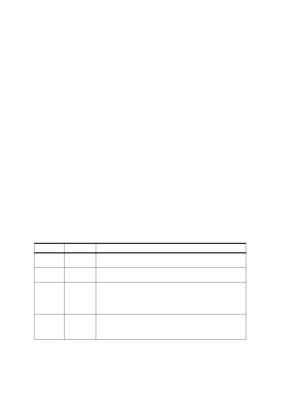
pages, structure elements occurring on the imported page are typically part of a larger structure pertaining
to the document as a whole; such elements cannot meaningfully be incorporated into the structure of the
containing document. In a one-page target document or one made up of independent, structurally
unrelated pages, the logical structure for the imported page may be wholly self-contained; in this case, it
may be possible to incorporate this structure information into that of the containing document. However,
PDF provides no mechanism for the logical structure hierarchy of one document to refer indirectly to that of
another.
8.11
Optional Content
8.11.1
General
Optional content (PDF 1.5) refers to sub-clauses of content in a PDF document that can be selectively viewed
or hidden by document authors or consumers. This capability is useful in items such as CAD drawings, layered
artwork, maps, and multi-language documents.
NOTE
The following sub-clauses describe the PDF structures used to implement optional content:
8.11.2, "Optional Content Groups", describes the primary structures used to control the visibility of content.
8.11.3, "Making Graphical Content Optional", describes how individual pieces of content in a document may
declare themselves as belonging to one or more optional content groups.
8.11.4, "Configuring Optional Content", describes how the states of optional content groups are set.
8.11.2
Optional Content Groups
8.11.2.1
General
An optional content group is a dictionary representing a collection of graphics that can be made visible or
invisible dynamically by users of conforming readers. The graphics belonging to such a group may reside
anywhere in the document: they need not be consecutive in drawing order, nor even belong to the same
content stream. Table 98 shows the entries in an optional content group dictionary.
Table 98 - Entries in an Optional Content Group Dictionary
Key
Type
Value
Type
name
(Required) The type of PDF object that this dictionary describes; shall be
OCG for an optional content group dictionary.
Name
text string
(Required) The name of the optional content group, suitable for
presentation in a reader’s user interface.
Intent
name
or
(Optional) A single intent name or an array containing any combination of
array
names. PDF defines two names, View and Design, that may indicate the
intended use of the graphics in the group. A conforming reader may
choose to use only groups that have a specific intent and ignore others.
Default value: View. See 8.11.2.3, "Intent" for more information.
Usage
dictionary
(Optional) A usage dictionary describing the nature of the content
controlled by the group. It may be used by features that automatically
control the state of the group based on outside factors. See 8.11.4.4,
"Usage and Usage Application Dictionaries" for more information.
In its simplest form, each dictionary shall contain a Type entry and a Name for presentation in a user interface.
It may also have an Intent entry that may describe its intended use (see 8.11.2.3, "Intent") and a Usage entry
that shall describe the nature of its content (see 8.11.4.4, "Usage and Usage Application Dictionaries").
222

Individual content elements in a document may specify the optional content group or groups that affect their
visibility (see 8.11.3, "Making Graphical Content Optional"). Any content whose visibility shall be affected by a
given optional content group is said to belong to that group.
A group shall be assigned a state, which is either ON or OFF. States themselves are not part of the PDF
document but may be set programmatically or through the reader’s user interface to change the visibility of
content. When a document is first opened by a conforming reader, the groups’ states shall be initialized based
on the document’s default configuration dictionary
(see
8.11.4.3, "Optional Content Configuration
Dictionaries").
Content belonging to a group shall be visible when the group is ON and invisible when it is OFF. Content may
belong to multiple groups, which may have conflicting states. These cases shall be described by the use of
optional content membership dictionaries, described in the next sub-clause.
8.11.2.2
Optional Content Membership Dictionaries
As mentioned above, content may belong to a single optional content group and shall be visible when the
group is ON and invisible when it is OFF. To express more complex visibility policies, content shall not declare
itself to belong directly to an optional content group but rather to an optional content membership dictionary,
whose entries are shown in Table 99.
NOTE 1
8.11.3, "Making Graphical Content Optional" describes how content declares its membership in a group or
membership dictionary.
Table 99 - Entries in an Optional Content Membership Dictionary
Key
Type
Value
Type
name
(Required) The type of PDF object that this dictionary describes; shall be
OCMD for an optional content membership dictionary.
OCGs
dictionary or
(Optional) A dictionary or array of dictionaries specifying the optional
array
content groups whose states shall determine the visibility of content
controlled by this membership dictionary.
Null values or references to deleted objects shall be ignored. If this entry is
not present, is an empty array, or contains references only to null or deleted
objects, the membership dictionary shall have no effect on the visibility of
any content.
P
name
(Optional) A name specifying the visibility policy for content belonging to
this membership dictionary. Valid values shall be:
AllOn
visible only if all of the entries in OCGs are ON
AnyOn visible if any of the entries in OCGs are ON
AnyOff visible if any of the entries in OCGs are OFF
AllOff
visible only if all of the entries in OCGs are OFF
Default value: AnyOn
VE
array
(Optional; PDF 1.6) An array specifying a visibility expression, used to
compute visibility of content based on a set of optional content groups; see
discussion below.
An optional content membership dictionary may express its visibility policy in two ways:
•
The P entry may specify a simple boolean expression indicating how the optional content groups specified
by the OCGs entry determine the visibility of content controlled by the membership dictionary.
•
PDF 1.6 introduced the VE entry, which is a visibility expression that may be used to specify an arbitrary
boolean expression for computing the visibility of content from the states of optional content groups.
223
NOTE 2
Since the VE entry is more general, if it is present and supported by the conforming reader software, it should
be used in preference to OCGs and P. However, for compatibility purposes, conforming writers should use
OCGs and P entries where possible. When the use of VE is necessary to express the intended behaviour,
OCGs and P entries should also be provided to approximate the behaviour in non-conforming reader software.
A visibility expression is an array with the following characteristics:
•
Its first element shall be a name representing a boolean operator (And, Or, or Not).
•
Subsequent elements shall be either optional content groups or other visibility expressions.
•
If the first element is Not, it shall have only one subsequent element. If the first element is And or Or, it
shall have one or more subsequent elements.
•
In evaluating a visibility expression, the ON state of an optional content group shall be equated to the
boolean value true; OFF shall be equated to false.
Membership dictionaries are useful in cases such as these:
•
Some content may choose to be invisible when a group is ON and visible when it is OFF. In this case, the
content would belong to a membership dictionary whose OCGs entry consists of a single optional content
group and whose P entry is AnyOff or AllOff.
NOTE 3
It is legal to have an OCGs entry consisting of a single group and a P entry that is AnyOn or AllOn. However,
in this case it is preferable to use an optional content group directly because it uses fewer objects.
•
Some content may belong to more than one group and needs to specify its policy when the groups are in
conflicting states. In this case, the content would belong to a membership dictionary whose OCGs entry
consists of an array of optional content groups and whose P entry specifies the visibility policy, as
illustrated in EXAMPLE 1 in this sub-clause. EXAMPLE 2 in this sub-clause shows the equivalent policy
using visibility expressions.
EXAMPLE 1
This example shows content belonging to a membership dictionary whose OCGs entry consists of an
array of optional content groups and whose P entry specifies the visibility policy.
<< /Type /OCMD
% Content belonging to this optional content
% membership dictionary is controlled by the states
/OCGs [12 0 R 13 0 R 14 0 R]
% of three optional content groups.
/P /AllOn
% Content is visible only if the state of all three
>>
% groups is ON; otherwise it’s hidden.
EXAMPLE 2
This example shows a visibility expression equivalent to EXAMPLE 1 in this sub-clause
<< /Type /OCMD
/VE [/And 12 0 R 13 0 R 14 0 R]
% Visibility expression equivalent to EXAMPLE 1.
>>
EXAMPLE 3
This example shows a more complicated visibility expression based on five optional content groups,
represented by objects 1 through 5. It is equivalent to
“OCG 1” OR (NOT “OCG 2”) OR (“OCG 3” AND “OCG 4” AND “OCG 5”)
<< /Type /OCMD
/VE [/Or
% Visibility expression: OR
1 0 R
% OCG 1
[/Not 2 0 R]
% NOT OCG 2
[/And 3 0 R 4 0 R 5 0 R]
% OCG 3 AND OCG 4 AND OCG 5
]
>>
224
8.11.2.3
Intent
PDF defines two intents: Design, which may be used to represent a document designer’s structural
organization of artwork, and View, which may be used for interactive use by document consumers. A
conforming writer shall not use a value other than Design or View.
NOTE
The Intent entry in Table 98 provides a way to distinguish between different intended uses of optional content.
For example, many document design applications, such as CAD packages, offer layering features for
collecting groups of graphics together and selectively hiding or viewing them for the convenience of the author.
However, this layering may be different (at a finer granularity, for example) than would be useful to consumers
of the document. Therefore, it is possible to specify different intents for optional content groups within a single
document. A conforming reader may decide to use only groups that are of a specific intent.
Configuration dictionaries (see 8.11.4.3, "Optional Content Configuration Dictionaries") may also contain an
Intent entry. If one or more of a group’s intents is contained in the current configuration’s set of intents, the
group shall be used in determining visibility. If there is no match, the group shall have no effect on visibility.
If the configuration’s Intent is an empty array, no groups shall be used in determining visibility; therefore, all
content shall be considered visible.
8.11.3
Making Graphical Content Optional
8.11.3.1
General
Graphical content in a PDF file may be made optional by specifying membership in an optional content group
or optional content membership dictionary. Two primary mechanisms exist for defining membership:
•
Sections of content streams delimited by marked-content operators may be made optional, as described in
8.11.3.2, "Optional Content in Content Streams".
•
Form and image XObjects and annotations may be made optional in their entirety by means of a dictionary
entry, as described in 8.11.3.3, "Optional Content in XObjects and Annotations".
When a piece of optional content in a PDF file is determined that it shall be hidden, the following occurs:
•
The content shall not be drawn.
•
Graphics state operations, such as setting the colour, transformation matrix, and clipping, shall still be
applied. In addition, graphics state side effects that arise from drawing operators shall be applied; in
particular, the current text position shall be updated even for text wrapped in optional content. In other
words, graphics state parameters that persist past the end of a marked-content section shall be the same
whether the optional content is visible or not.
Hiding a section of optional content shall not change the colour of objects that do not belong to the same
optional content group.
•
This rule shall also apply to operators that set state that is not strictly graphics state; for example, BX and
EX.
•
Objects such as form XObjects and annotations that have been made optional may be skipped entirely,
because their contents are encapsulated such that no changes to the graphics state (or other state) persist
beyond the processing of their content stream.
Other features in conforming readers, such as searching and editing, may be affected by the ability to
selectively show or hide content. A conforming reader may choose whether to use the document’s current state
of optional content groups (and, correspondingly, the document’s visible graphics) or to supply their own states
of optional content groups to control the graphics they process.
NOTE 4
Tools to select and move annotations should honour the current on-screen visibility of annotations when
performing cursor tracking and mouse-click processing. A full text search engine, however, may need to
225
process all content in a document, regardless of its current visibility on-screen. Export filters might choose the
current on-screen visibility, the full content, or present the user with a selection of OCGs to control visibility.
NOTE 5
A non-conforming reader that does not support optional content, such as one that only supports PDF 1.4
functionality, will draw and process all content in a document.
8.11.3.2
Optional Content in Content Streams
Sections of content in a content stream (including a page's Contents stream, a form or pattern’s content
stream, glyph descriptions a Type 3 font as specified by its CharProcs entry, or an annotation’s appearance)
may be made optional by enclosing them between the marked-content operators BDC and EMC (see 14.6,
"Marked Content") with a marked-content tag of OC. In addition, a DP marked-content operator may be placed
in a page’s content stream to force a reference to an optional content group or groups on the page, even when
the page has no current content in that layer.
The property list associated with the marked content shall specify either an optional content group or optional
content membership dictionary to which the content belongs. Because a group shall be an indirect object and a
membership dictionary contains references to indirect objects, the property list shall be a named resource listed
in the Properties subdictionary of the current resource dictionary (see 14.6.2, "Property Lists"), as shown in
EXAMPLE 1 and EXAMPLE 2 in this sub-clause.
Although the marked-content tag shall be OC, other applications of marked content are not precluded from
using OC as a tag. The marked content shall be considered to be for optional content only if the tag is OC and
the dictionary operand is a valid optional content group or optional content membership dictionary.
NOTE 1
To avoid conflict with other features that used marked content (such as logical structure; see 14.7, "Logical
Structure"), the following strategy is recommended:
Where content is to be tagged with optional content markers as well as other markers, the optional content
markers should be nested inside the other marked content.
Where optional content and the other markers would overlap but there is not strict containment, the optional
content should be broken up into two or more BDC/EMC sections, nesting the optional content sections inside
the others as necessary. Breaking up optional content spans does not damage the nature of the visibility of the
content, whereas the same guarantee cannot be made for all other uses of marked content.
NOTE 2
Any marked content tagged for optional content that is nested inside other marked content tagged for optional
content is visible only if all the levels indicate visibility. In other words, if the settings that apply to the outer level
indicate that the content should be hidden, the inner level is hidden regardless of its settings.
In the following example, the state of the Show Greeting optional content group directly controls the visibility of
the text string “Hello” on the page. When the group is ON, the text shall be visible; when the group is OFF, the
text shall be hidden.
EXAMPLE 1
% Within a content stream
/OC /oc1 BDC
% Optional content follows
BT
/F1 1 Tf
12 0 0 12 100 600 Tm
(Hello) Tj
ET
EMC
% End of optional content
<<
% In the resources dictionary
/Properties << /oc1 5 0 R >>
% This dictionary maps the name oc1 to an
% optional content group (object 5)
>>
5 0 obj
% The OCG controlling the visibility
226
<<
% of the text.
/Type /OCG
/Name (Show Greeting)
>>
endobj
The example above shows one piece of content associated with one optional content group. There are other
possibilities:
•
More than one section of content may refer to the same group or membership dictionary, in which case the
visibility of both sections is always the same.
•
Equivalently, although less space-efficient, different sections may have separate membership dictionaries
with the same OCGs and P entries. The sections shall have identical visibility behaviour.
•
Two sections of content may belong to membership dictionaries that refer to the same group(s) but with
different P settings. For example, if one section has no P entry, and the other has a P entry of AllOff, the
visibility of the two sections of content shall be opposite. That is, the first section shall be visible when the
second is hidden, and vice versa.
The following example demonstrates both the direct use of optional content groups and the indirect use of
groups through a membership dictionary. The content (a black rectangle frame) is drawn if either of the images
controlled by the groups named Image A or Image B is shown. If both groups are hidden, the rectangle frame
shall be hidden.
EXAMPLE 2
% Within a content stream
/OC /OC2 BDC
% Draws a black rectangle frame
0 g
4 w
100 100 412 592 re s
EMC
/OC /OC3 BDC
% Draws an image XObject
q
412 0 0 592 100 100 cm
/Im3 Do
Q
EMC
/OC /OC4 BDC
% Draws an image XObject
q
412 0 0 592 100 100 cm
/Im4 Do
Q
EMC
<<
% The resource dictionary
/Properties << /OC2 20 0 R /OC3 30 0 R /OC4 40 0 R >>
/XObject << /lm3 50 0 R /lm4 /60 0 R >>
>>
20 0 obj
<<
% Optional content membership dictionary
/Type /OCMD
/OCGs [30 0 R 40 0 R]
/P /AnyOn
>>
endobj
30 0 obj
% Optional content group “Image A”
<<
/Type /OCG
/Name (Image A)
227

>>
endobj
40 0 obj
% Optional content group “Image B”
<<
/Type /OCG
/Name (Image B)
>>
endobj
8.11.3.3
Optional Content in XObjects and Annotations
In addition to marked content within content streams, form XObjects and image XObjects (see 8.8, "External
Objects") and annotations (see 12.5, "Annotations") may contain an OC entry, which shall be an optional
content group or an optional content membership dictionary.
A form or image XObject's visibility shall be determined by the state of the group or those of the groups
referenced by the membership dictionary in conjunction with its P (or VE) entry, along with the current visibility
state in the context in which the XObject is invoked (that is, whether objects are visible in the contents stream at
the place where the Do operation occurred).
Annotations have various flags controlling on-screen and print visibility (see 12.5.3, "Annotation Flags"). If an
annotation contains an OC entry, it shall be visible for screen or print only if the flags have the appropriate
settings and the group or membership dictionary indicates it shall be visible.
8.11.4
Configuring Optional Content
8.11.4.1
General
A PDF document containing optional content may specify the default states for the optional content groups in
the document and indicate which external factors shall be used to alter the states.
NOTE
The following sub-clauses describe the PDF structures that are used to specify this information.
8.11.4.2, "Optional Content Properties Dictionary" describes the structure that lists all the optional content
groups in the document and their possible configurations.
8.11.4.3, "Optional Content Configuration Dictionaries" describes the structures that specify initial state
settings and other information about the groups in the document.
8.11.4.4, "Usage and Usage Application Dictionaries" and 8.11.4.5, "Determining the State of Optional Content
Groups" describe how the states of groups can be affected based on external factors.
8.11.4.2
Optional Content Properties Dictionary
The optional OCProperties entry in the document catalog (see 7.7.2, "Document Catalog") shall contain, when
present, the optional content properties dictionary, which contains a list of all the optional content groups in the
document, as well as information about the default and alternate configurations for optional content. This
dictionary shall be present if the file contains any optional content; if it is missing, a conforming reader shall
ignore any optional content structures in the document.
This dictionary contains the following entries:
Table 100 - Entries in the Optional Content Properties Dictionary
Key
Type
Value
OCGs
array
(Required) An array of indirect references to all the optional content
groups in the document (see 8.11.2, "Optional Content Groups"), in any
order. Every optional content group shall be included in this array.
228
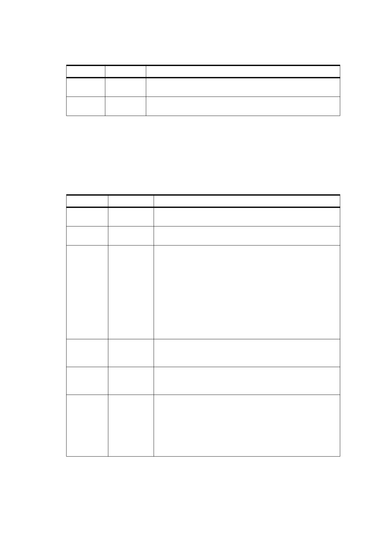
Table 100 - Entries in the Optional Content Properties Dictionary (continued)
Key
Type
Value
D
dictionary
(Required) The default viewing optional content configuration dictionary
(see 8.11.4.3, "Optional Content Configuration Dictionaries").
Configs
array
(Optional) An array of alternate optional content configuration
dictionaries (see 8.11.4.3, "Optional Content Configuration Dictionaries").
8.11.4.3
Optional Content Configuration Dictionaries
The D and Configs entries in Table 100 are configuration dictionaries, which represent different presentations
of a document’s optional content groups for use by conforming readers. The D configuration dictionary shall be
used to specify the initial state of the optional content groups when a document is first opened. Configs lists
other configurations that may be used under particular circumstances. The entries in a configuration dictionary
are shown in Table 101.
Table 101 - Entries in an Optional Content Configuration Dictionary
Key
Type
Value
Name
text string
(Optional) A name for the configuration, suitable for presentation in a
user interface.
Creator
text string
(Optional) Name of the application or feature that created this
configuration dictionary.
BaseState
name
(Optional) Used to initialize the states of all the optional content
groups in a document when this configuration is applied. The value of
this entry shall be one of the following names:
ON
The states of all groups shall be turned ON.
OFF
The states of all groups shall be turned OFF.
Unchanged The states of all groups shall be left unchanged.
After this initialization, the contents of the ON and OFF arrays shall be
processed, overriding the state of the groups included in the arrays.
Default value: ON.
If BaseState is present in the document’s default configuration
dictionary, its value shall be ON.
ON
array
(Optional) An array of optional content groups whose state shall be
set to ON when this configuration is applied.
If the BaseState entry is ON, this entry is redundant.
OFF
array
(Optional) An array of optional content groups whose state shall be
set to OFF when this configuration is applied.
If the BaseState entry is OFF, this entry is redundant.
Intent
name or array
(Optional) A single intent name or an array containing any
combination of names. it shall be used to determine which optional
content groups’ states to consider and which to ignore in calculating
the visibility of content (see 8.11.2.3, "Intent").
PDF defines two intent names, View and Design. In addition, the
name All shall indicate the set of all intents, including those not yet
defined. Default value: View. The value shall be View for the
document’s default configuration.
229

Table 101 - Entries in an Optional Content Configuration Dictionary (continued)
Key
Type
Value
AS
array
(Optional) An array of usage application dictionaries (see Table 103)
specifying which usage dictionary categories (see Table 102) shall be
consulted by conforming readers to automatically set the states of
optional content groups based on external factors, such as the current
system language or viewing magnification, and when they shall be
applied.
Order
array
(Optional) An array specifying the order for presentation of optional
content groups in a conforming reader’s user interface. The array
elements may include the following objects:
Optional content group dictionaries, whose Name entry shall be
displayed in the user interface by the conforming reader.
Arrays of optional content groups which may be displayed by a
conforming reader in a tree or outline structure. Each nested array
may optionally have as its first element a text string to be used as a
non-selectable label in a conforming reader’s user interface.
Text labels in nested arrays shall be used to present collections of
related optional content groups, and not to communicate actual
nesting of content inside multiple layers of groups (see EXAMPLE 1 in
8.11.4.3, "Optional Content Configuration Dictionaries"). To reflect
actual nesting of groups in the content, such as for layers with
sublayers, nested arrays of groups without a text label shall be used
(see EXAMPLE
2 in
8.11.4.3, "Optional Content Configuration
Dictionaries").
An empty array
[] explicitly specifies that no groups shall be
presented.
In the default configuration dictionary, the default value shall be an
empty array; in other configuration dictionaries, the default shall be
the Order value from the default configuration dictionary.
Any groups not listed in this array shall not be presented in any user
interface that uses the configuration.
ListMode
name
(Optional) A name specifying which optional content groups in the
Order array shall be displayed to the user. Valid values shall be:
AllPages
Display all groups in the Order array.
VisiblePages Display only those groups in the Order array that are
referenced by one or more visible pages.
Default value: AllPages.
RBGroups
array
(Optional) An array consisting of one or more arrays, each of which
represents a collection of optional content groups whose states shall
be intended to follow a radio button paradigm. That is, the state of at
most one optional content group in each array shall be ON at a time. If
one group is turned ON, all others shall be turned OFF. However,
turning a group from ON to OFF does not force any other group to be
turned ON.
An empty array [] explicitly indicates that no such collections exist.
In the default configuration dictionary, the default value shall be an
empty array; in other configuration dictionaries, the default is the
RBGroups value from the default configuration dictionary.
230

Table 101 - Entries in an Optional Content Configuration Dictionary (continued)
Key
Type
Value
Locked
array
(Optional; PDF 1.6) An array of optional content groups that shall be
locked when this configuration is applied. The state of a locked group
cannot be changed through the user interface of a conforming reader.
Conforming writers can use this entry to prevent the visibility of
content that depends on these groups from being changed by users.
Default value: an empty array.
A conforming reader may allow the states of optional content groups
from being changed by means other than the user interface, such as
JavaScript or items in the AS entry of a configuration dictionary.
NOTE
EXAMPLE 1 and EXAMPLE 2 in this sub-clause illustrate the use of the Order entry to control the display of
groups in a user interface.
EXAMPLE 1
Given the following PDF objects:
1 0 obj <</Type /OCG /Name (Skin)>> endobj
% Optional content groups
2 0 obj <</Type /OCG /Name (Bones)>> endobj
3 0 obj <</Type /OCG /Name (Bark)>> endobj
4 0 obj <</Type /OCG /Name (Wood)>> endobj
5 0 obj
% Configuration dictionary
<< /Order [[(Frog Anatomy) 1 0 R 2 0 R] [(Tree Anatomy) 3 0 R 4 0 R] ] >>
A conforming reader should display the optional content groups as follows:
Frog Anatomy
Skin
Bones
Tree Anatomy
Bark
Wood
EXAMPLE 2
Given the following PDF objects:
% Page contents
/OC /L1 BDC
% Layer 1
/OC /L1a BDC
% Sublayer A of layer 1
0 0 100 100 re f
EMC
/OC /L1b BDC
% Sublayer B of layer 1
0 100 100 100 re f
EMC
EMC
<< /L1 1 0 R
% Resource names
/L1a 2 0 R
/L1b 3 0 R
>>
%Optional content groups
1 0 obj <</Type /OCG /Name (Layer 1)>> endobj
2 0 obj <</Type /OCG /Name (Sublayer A)>> endobj
3 0 obj <</Type /OCG /Name (Sublayer B)>> endobj
4 0 obj
% Configuration dictionary
<< /Order [1 0 R [2 0 R 3 0 R]] >>
A conforming reader should display the OCGs as follows:
Layer 1
Sublayer A
Sublayer B
231

The AS entry is an auto state array consisting of one or more usage application dictionaries that specify how
conforming readers shall automatically set the state of optional content groups based on external factors, as
discussed in the following sub-clause.
8.11.4.4
Usage and Usage Application Dictionaries
Optional content groups are typically constructed to control the visibility of graphic objects that are related in
some way. Objects can be related in several ways; for example, a group may contain content in a particular
language or content suitable for viewing at a particular magnification.
An optional content group’s usage dictionary (the value of the Usage entry in an optional content group
dictionary; see Table 98) shall contain information describing the nature of the content controlled by the group.
This dictionary can contain any combination of the entries shown in Table 102.
Table 102 - Entries in an Optional Content Usage Dictionary
Key
Type
Value
CreatorInfo
dictionary
(Optional) A dictionary used by the creating application to store
application-specific data associated with this optional content group. It
shall contain two required entries:
Creator
A text string specifying the application that created the group.
Subtype A name defining the type of content controlled by the group.
Suggested values include but shall not be limited to Artwork,
for graphic-design or publishing applications, and Technical,
for technical designs such as building plans or schematics.
Additional entries may be included to present information relevant to the
creating application or related applications.
Groups whose Intent entry contains Design typically include a
CreatorInfo entry.
Language
dictionary
(Optional) A dictionary specifying the language of the content controlled by
this optional content group. It may contain the following two entries:
Lang
(required) A text string that specifies a language and possibly
a locale (see 14.9.2, "Natural Language Specification"). For
example, es-MX represents Mexican Spanish.
Preferred
(optional) A name whose values shall be either ON or OFF.
Default value: OFF. it shall be used by conforming readers
when there is a partial match but no exact match between the
system language and the language strings in all usage
dictionaries. See
8.11.4.4, "Usage and Usage Application
Dictionaries" for more information.
Export
dictionary
(Optional) A dictionary containing one entry, ExportState, a name whose
value shall be either ON or OFF. This value shall indicate the
recommended state for content in this group when the document (or part of
it) is saved by a conforming reader to a format that does not support
optional content (for example, a raster image format).
Zoom
dictionary
(Optional) A dictionary specifying a range of magnifications at which the
content in this optional content group is best viewed. It shall contain one or
both of the following entries:
min
The minimum recommended magnification factor at which the
group shall be ON. Default value: 0.
max
The magnification factor below which the group shall be ON.
Default value: infinity.
232