Toyota FJ Cruiser (GSJ 10, 15 series). Manual - part 349
PM–20
PARK ASSIST / MONITORING – CLEARANCE SONAR SYSTEM
PM
DESCRIPTION
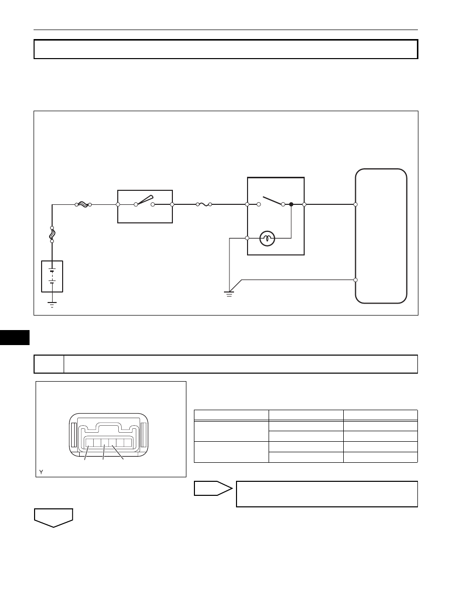
Turning this switch on activates the clearance sonar system.
WIRING DIAGRAM
INSPECTION PROCEDURE
(a) Remove the back sonar switch.
(b) Check the resistance.
Standard resistance
(c) Reinstall the back sonar switch.
NG
OK
Clearance Sonar Main Switch Circuit
1
INSPECT BACK SONAR SWITCH ASSEMBLY
Clearance Warning ECU
Assembly
+B
E
ECU
E
IG
AM1
AM1
IG1
IG1
Back Sonar Switch
Assembly
Ignition Switch
ALT
Battery
B132696E02
6
6 5 4 3 2 1
ECU
E
IG
Back Sonar Switch:
I102377E02
Tester Connection
Switch Condition
Specified Condition
3 (IG) - 4 (ECU)
Back sonar switch ON
Below 1
Ω
Back sonar switch OFF
1 M
Ω or higher
3 (IG) - 6 (E)
Back sonar switch ON
Below 30
Ω
Back sonar switch OFF
10 k
Ω or higher
REPLACE BACK SONAR SWITCH
ASSEMBLY