Toyota FJ Cruiser (GSJ 10, 15 series). Manual - part 338
 

  Index      Toyota     Toyota FJ Cruiser (model GSJ 10, 15 series) - service repair manual 2007 year


Search            


Content   ..  336  337  338  339   ..


Toyota FJ Cruiser (GSJ 10, 15 series). Manual - part 338


MI–8

MIRROR  –  OUTER REAR VIEW MIRROR

MI

REMOVAL

HINT:

Use the same procedure for both the RH and LH sides.

The procedure described below is for the LH side.

1.

DISCONNECT CABLE FROM NEGATIVE BATTERY 
TERMINAL

2.

REMOVE FRONT ARMREST BASE UPPER PANEL 
(See page 

WS-25

)

3.

REMOVE FRONT DOOR TRIM BOARD SUB-
ASSEMBLY
HINT:
Use the same procedure as for the RH side (see page 

ED-9

).

4.

REMOVE NO. 2 FRONT DOOR SERVICE HOLE 
COVER
HINT:
Use the same procedure as for the RH side (see page 

ED-10

).

5.

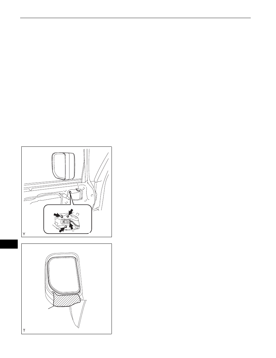
REMOVE OUTER REAR VIEW MIRROR
(a) Driver side:

Provisionally install the power window regulator 
master switch.

(b) Passenger side:

Provisionally install the power window regulator 
switch.

(c) Close the door glass.
(d) Disconnect the connector.
(e) Remove the 3 bolts and the outer rear view mirror.

NOTICE:
Do not drop or damage the outer rear view 
mirror when removing the bolts.

(f)

Apply protective tape to the lower part of the mirror 
body.

(g) Press down the upper part of the mirror and tilt the 

mirror.

B135564

Protective 
Tape

B140036E01

MIRROR  –  OUTER REAR VIEW MIRROR

MI–9

MI

(h) Using a screwdriver with its tip wrapped in 

protective tape, insert it between the mirror holder 
and the mirror holder base.

(i)

Twist and disengage the 2 clips on the lower side of 
the mirror.
HINT:
Heating the mirror holder with a domestic dryer 
before this procedure makes the work easier.

(j)

While holding the mirror with the screwdriver, 
disengage the 4 clips and 2 claws on the upper side 
of the mirror and remove the mirror.

(k) Driver side:

Remove the power window regulator master switch.

(l)

Passenger side:
Remove the power window regulator switch.

6.

REMOVE OUTER REAR VIEW MIRROR 
ILLUMINATION LIGHT BULB (w/ Illumination)
(a) Turn the outer rear view mirror illumination light 

socket and bulb, in the direction indicated by the 
allow in the illustration, to remove them.

(b) Remove the outer rear view mirror illumination light 

bulb from the light socket.

Mirror Holder

Mirror Holder 
Base

B140035E01

Protective Tape

B138150E01

E127190

MI–10

MIRROR  –  OUTER REAR VIEW MIRROR

MI

INSPECTION

1.

INSPECT OUTER REAR VIEW MIRROR ASSEMBLY 
LH
(a) Check the operation.

(1) Apply battery voltage to the outer rear view 

mirror and check the operation of the outer rear 
view mirror.
Standard

If the result is not as specified, replace the 
outer rear view mirror.

2.

INSPECT OUTER REAR VIEW MIRROR ASSEMBLY 
RH
(a) Check the operation.

(1) Apply battery voltage to the outer rear view 

mirror and check the operation of the outer rear 
view mirror.
Standard

If the result is not as specified, replace the 
outer rear view mirror.

3.

INSPECT OUTER REAR VIEW MIRROR 
ILLUMINATION LIGHT
(a) Check the illumination operation.

(1) Connect the positive (+) battery lead to terminal 

2 and the negative (-) battery lead to terminal 1, 
then check that the illumination illuminates.
Standard:

Illumination illuminates.

If the illumination does not illuminate, check the 
faulty bulb.

1

2

3

4

5

B135566

Measurement Condition

Mirror Assembly Operation

Battery positive (+) - Terminal 3 (MV)

Battery negative (-) - Terminal 4 (COM)

Turns upward

Battery positive (+) - Terminal 4 (COM)

Battery negative (-) - Terminal 3 (MV)

Turns downward

Battery positive (+) - Terminal 5 (MH)

Battery negative (-) - Terminal 4 (COM)

Turns left

Battery positive (+) - Terminal 4 (COM)

Battery negative (-) - Terminal 5 (MH)

Turns right

1

2

3

4

5

B135567

Measurement Condition

Mirror Assembly Operation

Battery positive (+) - Terminal 3 (MV)

Battery negative (-) - Terminal 4 (COM)

Turns upward

Battery positive (+) - Terminal 4 (COM)

Battery negative (-) - Terminal 3 (MV)

Turns downward

Battery positive (+) - Terminal 5 (MH)

Battery negative (-) - Terminal 4 (COM)

Turns left

Battery positive (+) - Terminal 4 (COM)

Battery negative (-) - Terminal 5 (MH)

Turns right

1

2

3

4

5

B140027

MIRROR  –  OUTER REAR VIEW MIRROR

MI–11

MI

(b) Inspect the bulb.

(1) Inspect continuity of the bulb by connecting the 

tester.
Standard:

Continuity.

If continuity exists, replace the outer rear view 
mirror.
If no continuity exists, replace the bulb.

INSTALLATION

1.

INSTALL OUTER REAR VIEW MIRROR 
ILLUMINATION LIGHT BULB (w/ Illumination)
(a) Install the outer rear view mirror illumination light 

bulb into the light socket.

(b) Turn the outer rear view mirror illumination light 

socket and bulb, in the direction indicated by the 
arrow in the illustration, to install them.

2.

INSTALL OUTER REAR VIEW MIRROR
(a) Engage the 2 claws on the upper side of the mirror 

and the 6 clips and install the mirror.
HINT:
Heating the mirror holder with a domestic dryer 
before this procedure makes the work easier.

E127191

B138151


Content   ..  336  337  338  339   ..