Toyota FJ Cruiser (GSJ 10, 15 series). Manual - part 186
 

  Index      Toyota     Toyota FJ Cruiser (model GSJ 10, 15 series) - service repair manual 2007 year


Search            


Content   ..  184  185  186  187   ..


Toyota FJ Cruiser (GSJ 10, 15 series). Manual - part 186


1GR-FE ENGINE MECHANICAL  –  ENGINE UNIT

EM–175

EM

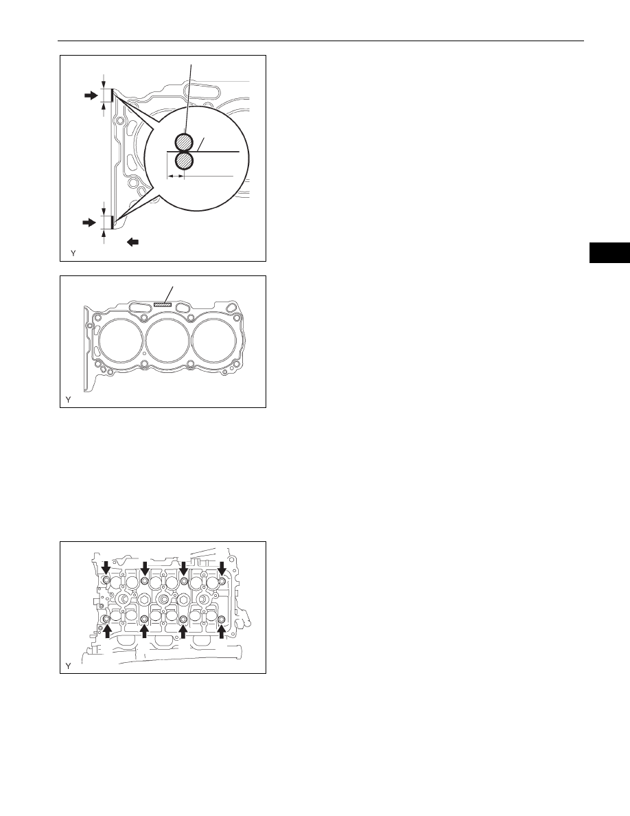
(b) Apply a continuous bead of seal packing (diameter 

2.5 to 3 mm (0.098 to 0.118 in.)) to a new cylinder 
head gasket as shown in the illustration.
Seal packing:

Toyota Genuine Seal Packing Black, Three 
Bond 1207B or the equivalent

NOTICE:
Install the cylinder head within 3 minutes of 
applying the seal packing. After installation, 
cylinder head bolts must be tightened within 15 
minutes. Otherwise, the seal packing must be 
removed and reapplied.

(c) Place the cylinder head gasket on the cylinder block 

surface with the Lot No. stamp upward.
NOTICE:

Install the cylinder head gasket in the correct 
direction.

Place the cylinder head carefully in order not 
to damage the gasket with the bottom part of 
the head.

19. INSTALL CYLINDER HEAD SUB-ASSEMBLY

(a) Place the cylinder head RH on the cylinder head 

gasket.

(b) Install the 8 cylinder head bolts.

HINT:

The cylinder head bolts are tightened in 2 
successive steps (steps (*1), (*2) and (*3)).

If any cylinder head bolts are broken or 
deformed, replace them.

(1) Apply a light coat of engine oil to the threads 

and under the heads of the cylinder head bolts.

(2) Using several steps, uniformly install and 

tighten the 10 cylinder head bolts and plate 
washers with a bi-hexagon wrench 10 mm in 
the sequence shown in the illustration.
Torque: 36 N*m (367 kgf*cm, 27 ft.*lbf)
If any cylinder head bolts do not meet the 
torque specification, replace them.
NOTICE:
Do not drop the washers into the cylinder 
head.

10 to 15 mm

10 to 15 mm

1.25 to 1.5 mm

Seal Packing

Gasket

Ǿ 2.5 to 3 mm

A076271E02

Lot No.

A076272E03

1

7

8

6

5

4

3

2

A076273E02

EM–176

1GR-FE ENGINE MECHANICAL  –  ENGINE UNIT

EM

(3) Mark the front of the cylinder head bolt with 

paint. (*1)

(4) Retighten the cylinder head bolts by 180

° as 

shown. (*2)

(5) Check that the painted marks are now at 180

° 

from the engine front. (*3)

20. INSTALL NO. 2 CYLINDER HEAD GASKET

(a) Remove any old packing material and oil from the 

contact surfaces of the cylinder head and cylinder 
block.

(b) Apply a continuous bead of seal packing (Diameter 

2.5 to 3 mm (0.098 to 0.118 in.)) to a new cylinder 
head gasket as shown in the illustration.
Seal packing:

Toyota Genuine Seal Packing Black, Three 
Bond 1207B or the equivalent

NOTICE:
Install the cylinder head within 3 minutes of 
applying the seal packing. After installation, 
cylinder head bolts must be tightened within 15 
minutes. Otherwise, the seal packing must be 
removed and reapplied.

(c) Place the cylinder head gasket on the cylinder block 

surface with the Lot No. stamp upward.
NOTICE:

Be careful of the installation direction.

Place the cylinder head carefully in order not 
to damage the gasket with the bottom part of 
the head.

21. INSTALL CYLINDER HEAD LH

(a) Place the cylinder head LH on the cylinder head 

gasket.

(b) Install the 8 cylinder head bolts.

HINT:

The cylinder head bolts are tightened in 2 
successive steps (steps (*4), (*5) and (*6)).

If any cylinder head bolts are broken or 
deformed, replace them.

(1) Apply a light coat of engine oil to the threads 

and under the heads of the cylinder head bolts.

180°

Engine 
Front

Paint Mark

A076274E02

10 to 15 mm

10 to 15 mm

Seal Packing

1.25 to 1.5 mm

Gasket

Ǿ 2.5 to 3 mm

A076275E02

Lot No.

A076276E02

1GR-FE ENGINE MECHANICAL  –  ENGINE UNIT

EM–177

EM

(2) Using several steps, uniformly install and 

tighten the 8 cylinder head bolts and plate 
washers with a bi-hexagon wrench 10 mm in 
the sequence shown in the illustration.
Torque: 36 N*m (367 kgf*cm, 27 ft.*lbf)
If any cylinder head bolts do not meet the 
torque specification, replace them.
NOTICE:
Do not drop the washers into the cylinder 
head.

(3) Mark the front of the cylinder head bolt with 

paint. (*4)

(4) Retighten the cylinder head bolts by 180

° as 

shown. (*5)

(5) Check that the painted marks are now at 180

° 

from the engine front. (*6)

(c) Install the 2 cylinder head bolts.

(1) Apply a light coat of engine oil to the threads of 

the cylinder head bolts.

(2) Using several steps, uniformly install and 

tighten the 10 cylinder head bolts and plate 
washers with a bi-hexagon wrench 10 mm in 
the sequence shown in the illustration.
Torque: 30 N*m (306 kgf*cm, 22 ft.*lbf)

22. INSTALL NO. 1 CAMSHAFT BEARING

(a) Align the bearing claw with the claw groove of the 

bearing cap, and push in the camshaft bearing.
NOTICE:

Install the bearing while aligning it with the oil 
hole in the bearing cap.

Clean the back side of the bearing and the 
surface of the bearing cap and keep them free 
of oil.

23. INSTALL NO. 2 CAMSHAFT BEARING

(a) Install the No. 2 camshaft bearing onto the cylinder 

head.
NOTICE:
Clean the back side of the bearing and the 
bearing surface of the cylinder head and keep 
them free of oil.

1

5

6

4

7

8

3

2

A076277E01

180°

Engine 
Front

Paint Mark

A076274E02

1

2

A072969E05

Claw

A126364E01

A076279E01

EM–178

1GR-FE ENGINE MECHANICAL  –  ENGINE UNIT

EM

24. INSTALL CAMSHAFTS

NOTICE:
Keep the camshaft level while it is being removed. 
The camshaft thrust clearance is very small and 
failing to keep it level could crack or damage the 
cylinder head journal surface, which receives the 
thrust force. This could subsequently lead the 
camshaft to seize or break. Perform the following 
steps to avoid such problems.

(a) Set the crankshaft position.

(1) Using the crankshaft pulley set bolt, turn the 

crankshaft, and set the crankshaft set key in 
the left horizontal position as indicated.
NOTICE:
Setting the crankshaft at the wrong angle 
could cause the piston head and valve head 
to come into contact with each other when 
the camshaft is installed. This could cause 
damage, so always set the camshaft at the 
correct angle.

(b) Apply new engine oil to the thrust portion and 

journal of the camshafts.

(c) Install the camshafts of bank 1.

(1) Place the 2 camshafts on the cylinder head RH 

with the No. 1 cam lobes facing as shown the 
illustration.

(2) Install the 8 bearing caps in their correct 

locations.

(3) Apply a light coat of engine oil to the threads of 

the bearing cap bolts.

90°

Set Key

Turn

A076280E02

Bank 1:

A076281E05

Bank 1:

A076282E05


Content   ..  184  185  186  187   ..