Toyota FJ Cruiser (GSJ 10, 15 series). Manual - part 142
 

  Index      Toyota     Toyota FJ Cruiser (model GSJ 10, 15 series) - service repair manual 2007 year


Search            


Content   ..  140  141  142  143   ..


Toyota FJ Cruiser (GSJ 10, 15 series). Manual - part 142


EM–2

1GR-FE ENGINE MECHANICAL  –  ENGINE

EM

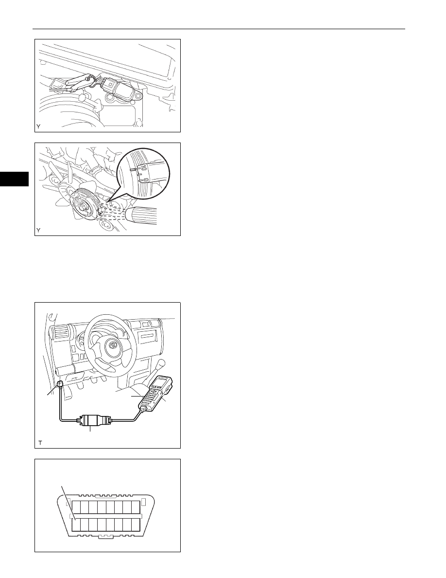
(3) Pull out the wire harness shown in the 

illustration.

(4) Connect the tester probe of a timing light to the 

wire of the ignition coil connector for the No. 1 
cylinder.
NOTICE:

Use timing light that detects the first 
signal.

After checking, wrap the wire harness 
with tape.

(5) Inspect the ignition timing during idling.

Ignition timing:

8 to 12

°CA BTDC during idling 

(Transmission in neutral position)

(6) Remove SST from the DLC3.
(7) Inspect the ignition timing during idling.

Ignition timing:

7 to 24

°CA BTDC during idling 

(Transmission in neutral position)

(8) Install the air cleaner.

8.

INSPECT ENGINE IDLING SPEED
NOTICE:

Turn all the electrical systems OFF.

Operate the inspection when the cooling fan 
motor is turned OFF.

(a) Warm up the engine.

(b) When using the intelligent tester:

(1) Connect the intelligent tester to the DLC3.
(2) Select the following menu items: DIAGNOSIS / 

ENHANCED OBD ll / DATA LIST / PRIMARY / 
ENGINE SPD.

(3) Inspect the engine idling speed.

Idling speed:

650 to 750 rpm (Transmission in neutral 
position)

(c) When not using the intelligent tester:

(1) Using SST, connect the terminal 8 (TAC) of the 

DLC3.
SST

09843-18030

(2) Race the engine speed at 2,500 rpm for 

approximately 90 seconds.

(3) Inspect the engine idling speed.

Idling speed:

650 to 750 rpm (Transmission in neutral 
position)

A076315E02

A076316E01

Intelligent Tester

DLC3

CAN VIM

A129958E01

1 2 3 4 5 6

9 1011 1213141516

7 8

TAC

DLC3

A118802E02

1GR-FE ENGINE MECHANICAL  –  ENGINE

EM–3

EM

9.

INSPECT COMPRESSION
(a) Warm up and stop the engine.
(b) Remove the circuit opening relay (See page 

ES-

443

).

(c) Remove the V-bank cover (See page 

ES-414

).

(d) Remove the air cleaner assembly (See page 

ES-

429

).

(e) Remove the throttle body bracket (See page 

FU-

11

).

(f)

Remove the oil baffle plate (See page 

FU-11

).

(g) Remove the No. 1 surge tank stay (See page 

FU-

11

).

(h) Remove the No. 2 surge tank stay (See page 

FU-

12

).

(i)

Remove the ignition coils (See page 

IG-8

).

(j)

Remove the spark plugs.

(k) Inspect the cylinder compression pressure.

(1) Insert a compression gauge into the spark plug 

hole. (*1)
SST

09992-00500

(2) Fully open the throttle. (*2)
(3) While cranking the engine, measure the 

compression pressure. (*3)
Compression pressure:

1,300 kPa (13.3 kgf/cm

2

, 189 psi)

Minimum pressure:

1,000 kPa (10.2 kgf/cm

2

, 145 psi)

Difference between cylinders:

100 kPa (1.0 kgf/cm

2

, 15 psi)

NOTICE:

Use a fully-charged battery so the engine 
speed can be increased to 2,500 rpm or 
more.

Inspect the other cylinders in the same 
way.

Measure the compression in as short a 
time as possible.

(4) If the cylinder compression is low, pour a small 

amount of engine oil into the cylinder through 
the spark plug hole and repeat steps (*1) 
through (*3) for cylinders with low compression.

If adding oil increases the compression, the 
piston rings and/or cylinder bore may be 
worn or damaged.

If the pressure stays low, a valve may be 
stuck or seated improperly, or there may be 
leakage from the gasket.

10. INSPECT CO/HC

(a) Start the engine.
(b) Run the engine at 2,500 rpm for approximately 180 

seconds.

(c) Insert the CO/HC meter testing probe at least 40 cm 

(1.3 ft) into the tailpipe during idling.

A076317E01

EM–4

1GR-FE ENGINE MECHANICAL  –  ENGINE

EM

(d) Immediately check the CO/HC concentration during 

idling and/or while running at 2,500 rpm.
HINT:

Complete the measurement within 3 minutes.

When carrying out the 2 mode (with the engine 
idling/running at 2,500 rpm) test, the 
measurement orders are prescribed by the 
applicable local regulations.

(e) If the CO/HC concentration does not comply with 

regulations, troubleshoot in the order given below.
(1) Check the heated oxygen sensor operation.

CO

HC

Problems

Causes

Normal

High

Rough idling

1.

Faulty ignition:

Incorrect timing

Fouled, shorted or improperly gapped plugs

2.

Incorrect valve clearance

3.

Leaking intake and exhaust valves

4.

Leaking cylinders

Low

High

Rough idling 
(Fluctuating HC reading)

1.

Vacuum leaks:

PCV hoses

Intake manifold

Throttle body

IAC  valve

Brake booster line

2.

Lean mixture causing misfire

High

High

Rough idling 
(Black smoke from 
exhaust)

1.

Restricted air filter

2.

Plugged PCV valve

3.

Faulty EFI systems:

Faulty pressure regulator

Faulty engine coolant temperature sensor

Faulty mass air flow meter

Faulty  ECM

Faulty injectors

Faulty throttle position sensor

1GR-FE ENGINE MECHANICAL  –  DRIVE BELT

EM–5

EM

ENGINE

1GR-FE ENGINE MECHANICAL

DRIVE BELT

COMPONENTS

FAN AND GENERATOR 
V BELT

NO. 1 ENGINE UNDER 
COVER SUB-ASSEMBLY

N*m (kgf*cm, ft*lbf)  : Specified torque

29 (296, 21)

x4

A126409E01


Content   ..  140  141  142  143   ..