Toyota FJ Cruiser (GSJ 10, 15 series). Manual - part 7
 

  Index      Toyota     Toyota FJ Cruiser (model GSJ 10, 15 series) - service repair manual 2007 year


Search            


Content   ..  5  6  7  8   ..


Toyota FJ Cruiser (GSJ 10, 15 series). Manual - part 7


1GR-FE EMISSION CONTROL  –  CANISTER

EC–9

EC

REMOVAL

1.

DISCHARGE FUEL SYSTEM PRESSURE
(See page

FU-1

)

2.

DISCONNECT CABLE FROM NEGATIVE BATTERY 
TERMINAL

3.

REMOVE CHARCOAL CANISTER ASSEMBLY
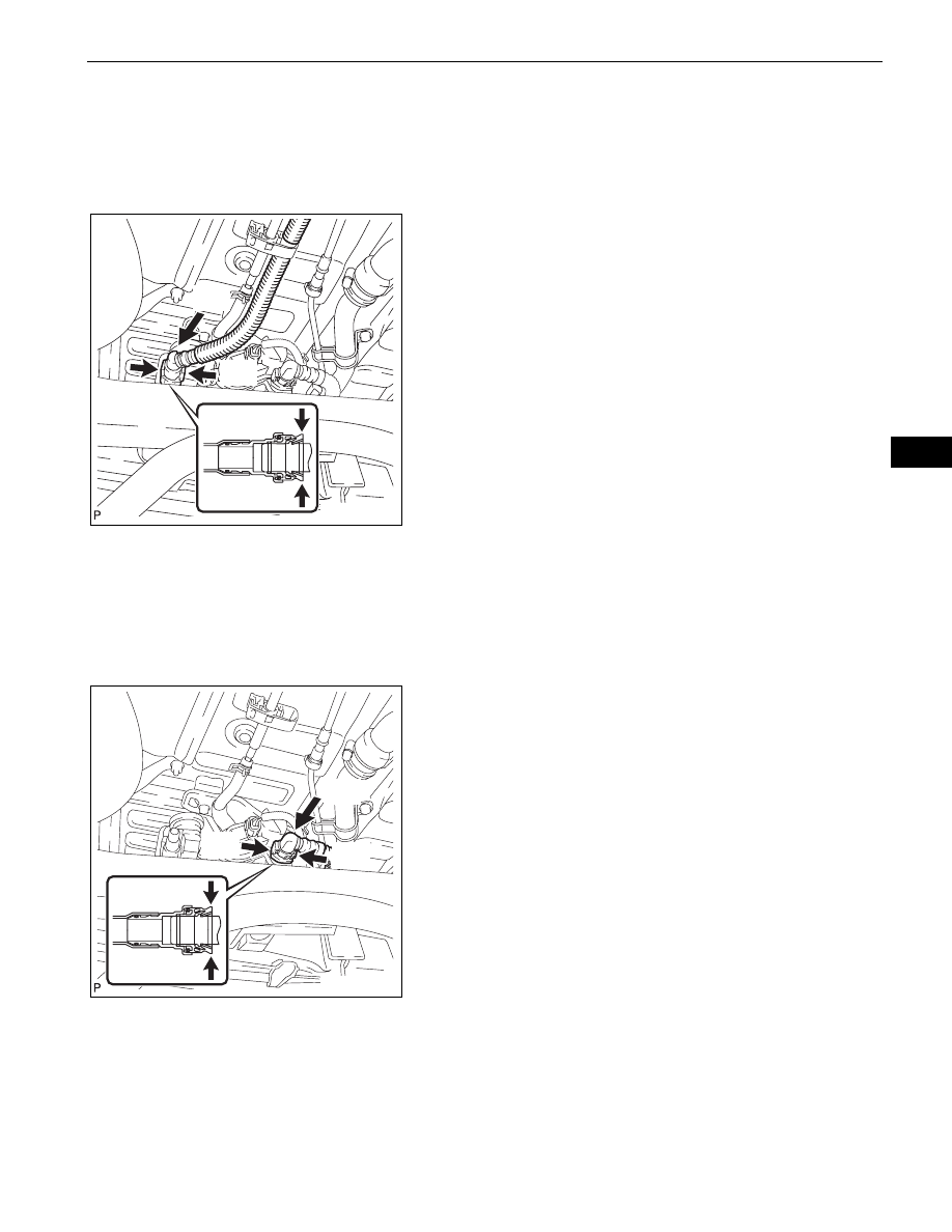
(a) Disconnect the fuel tank breather tube from the fuel 

tank.
(1) Push the connector deep inside.
(2) Pinch portion A, as shown in the illustration.
(3) Pull out the connector.

NOTICE:

Remove any dirt and foreign objects from 
the fuel tank vent hose connector before 
performing the work.

Do not allow any scratches or foreign 
objects on the parts when disconnecting, 
as the fuel tank vent hose connector has 
the O-ring that seals the pipe.

Perform the work by hand. Do not use 
any tools.

Do not forcibly bend, twist or turn the 
nylon tube.

Protect the disconnected part by 
covering it with a vinyl bag after 
disconnecting the fuel tank vent hose.

If the fuel vent connector and pipe are 
stuck, push and pull them to release.

(b) Disconnect the No. 2 canister outlet hose sub-

assembly.
(1) Push the connector deep inside.
(2) Pinch portion A, as shown in the illustration.
(3) Pull out the connector.

NOTICE:

Remove any dirt and foreign objects from 
the fuel tank vent hose connector before 
performing the work.

Do not allow any scratches or foreign 
objects on the parts when disconnecting, 
as the fuel tank vent hose connector has 
the O-ring that seals the pipe.

Perform the work by hand. Do not use 
any tools.

Do not forcibly bend, twist or turn the 
nylon tube.

Protect the disconnected part by 
covering it with a vinyl bag after 
disconnecting the fuel tank vent hose.

If the fuel vent connector and pipe are 
stuck, push and pull them to release.

A

A

Pinch

Push

Pinch

A129925E01

A

A

Pinch

Push

Pinch

A129926E01

EC–10

1GR-FE EMISSION CONTROL  –  CANISTER

EC

(c) Disconnect the connector.

(d) Disconnect the EVAP hose.

(e) Remove 3 bolts, then remove charcoal the canister 

assembly.

INSPECTION

1.

INSPECT CHARCOAL CANISTER ASSEMBLY
(a) Visually check the charcoal canister for cracks and 

damage.
If there is any cracks or damage, replace the 
charcoal canister assembly.

(b) Check the charcoal canister operation.

(1) While holding the purge port closed, blow 

pressurized air at 1.67 kPa (17.0 gf/cm

2

, 0.24 

psi) into the vent port, and check that the air 
flows from the air inlet port.
If the result is not as specified, replace the 
charcoal canister assembly.

A129928

A129927

A129929

A129951

Air

Vent Port

Purge Port

Air Inlet Port

A129952E01

1GR-FE EMISSION CONTROL  –  CANISTER

EC–11

EC

(2) While holding the vent port closed, apply a 

vacuum of 1.10 kPa (8.3 mmHg, 0.32 in.Hg) 
into the purge port, and check that the air flows 
from the air inlet port.
If the result is not as specified, replace the 
charcoal canister assembly.

(c) Check for air leakage.

(1) Remove the air hose between ports A and B.

(2) Connect the pressure gauge to the vent port of 

the charcoal canister.
SST

09992-00242

(3) While holding port B, the purge port and air 

inlet port closed with your fingers, leave port A 
open and apply pressurized air at 19.6 kPa (0.2 

kgf/cm

2

, 2.81 psi) into the vent port. Check that 

the pressure is retained.
If the result is not as specified, replace the 
charcoal canister assembly.

(d) Check the leak detection pump.

(1) Check that air flows from port A to ports B and 

C.
If the result is not as specified, replace the 
pump module.

(2) Apply battery positive voltage across the 

terminals.

(3) Check that the valve is closed.

If the result is not as specified, replace the 
pump module.

Vacuum

Purge Port

Air Inlet Port

Vent Port

A129953E01

A129954

Port A

Purge Port

Air Inlet Port

Port B

Vent Port

Pressure 
Gauge

A129955E01

C

B

A

Air

A129956E01

Valve

Closed

Battery

A129957E01

EC–12

1GR-FE EMISSION CONTROL  –  CANISTER

EC

INSTALLATION

1.

INSTALL CHARCOAL CANISTER ASSEMBLY
(a) Install the canister with the 3 bolts.

Torque: 20 N*m (204 kgf*cm, 15 ft.*lbf)

(b) Connect the connector.

(c) Connect the EVAP hose.

(d) Connect the No. 2 canister outlet hose sub-

assembly.
(1) Align the fuel tank vent hose connector with the 

pipe, then push in the fuel tank vent connector 
until the retainer makes a "click" sound to 
connect the fuel tank vent hose to the charcoal 
canister.
NOTICE:

Check that there are no scratches or 
foreign objects on the disconnected 
parts of the fuel tank vent connector and 
pipe before performing the work.

After connecting the fuel tank vent hose, 
check that the fuel tank vent hose is 
securely connected by pulling the quick 
connector.

A129929

A129927

A129928

Push

A129926E02


Content   ..  5  6  7  8   ..