Toyota FJ Cruiser (GSJ 10, 15 series). Manual - part 1


  Index      Toyota     Toyota FJ Cruiser (model GSJ 10, 15 series) - service repair manual 2007 year


Search                


Content   ..  1  2  3   ..


Toyota FJ Cruiser (GSJ 10, 15 series). Manual - part 1


DOOR LOCK  –  BACK DOOR LOCK

DL–117

DL

(b) Remove the back door lock cylinder.

INSPECTION

1.

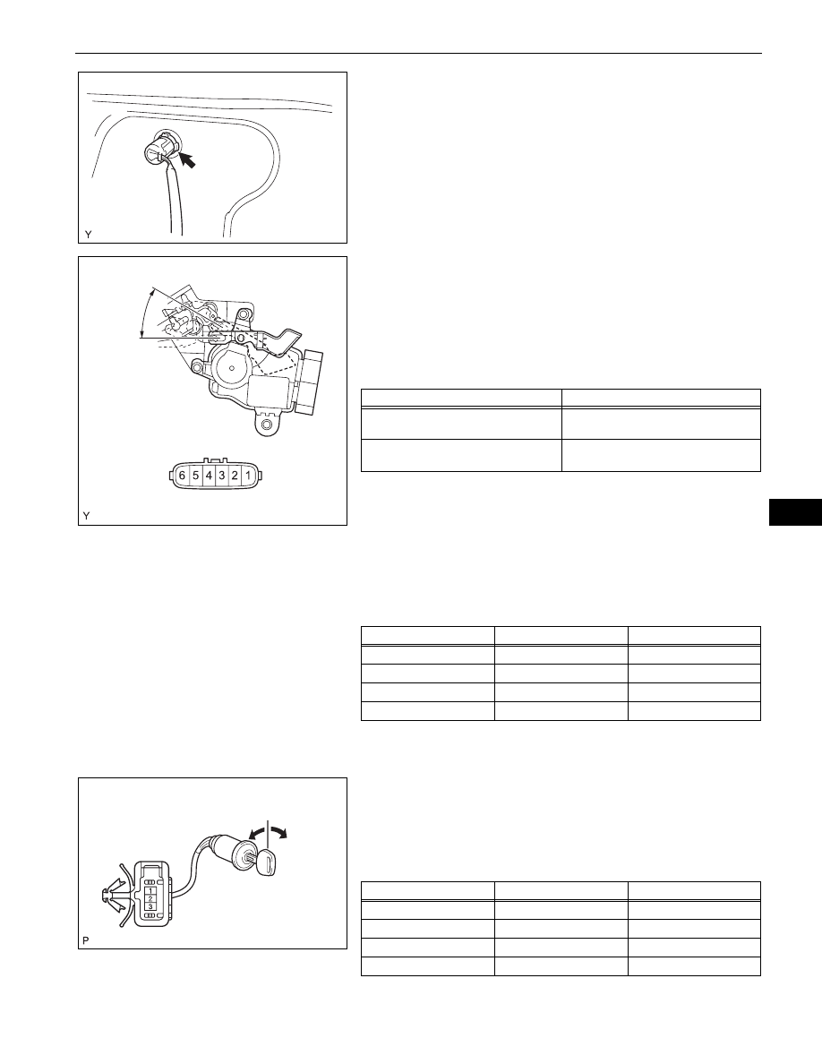
INSPECT BACK DOOR LOCK
(a) Check the operation of the back door lock actuator.

(1) Apply battery voltage to the back door lock 

actuator and check the operation of the back 
door lock motor.
Standard

If the result is not as specified, replace the back 
door lock.

(b) Check the resistance of the door lock and unlock 

switch.
(1) Using an ohmmeter, measure the resistance 

and check the results in accordance with the 
value(s) in the table below.
Standard Resistance

If the result is not as specified, replace the back 
door lock.

2.

INSPECT BACK DOOR LOCK CYLINDER
(a) Check the resistance.

(1) Using an ohmmeter, measure the resistance 

between the terminals when the cylinder is 
operated with a key.
Standard Resistance

If the result is not as specified, replace the back 
door lock cylinder.

B135548

Lock

Unlock

B135520E02

Measurement Condition

Specified Condition

Battery positive (+) 

 Terminal 2

Battery negative (-) 

 Terminal 1

Unlocks

Battery positive (+) 

 Terminal 1

Battery negative (-) 

 Terminal 2

Locks

Tester Connection

Door Lock Condition

Specified Condition

4 - 5

Unlocked

Below 1 

4 - 5

Locked

10 k

 or higher

4 - 6

Unlocked

10 k

 or higher

4 - 6

Locked

Below 1 

Unlock

Lock

B140025E01

Tester Connection

Condition

Specified Condition

1 - 2

Locked

Below 1 

1 - 2

Unlocked

10 k

 or higher

1 - 3

Locked

10 k

 or higher

1 - 3

Unlocked

Below 1 

DL–118

DOOR LOCK  –  BACK DOOR LOCK

DL

INSTALLATION

1.

INSTALL BACK DOOR LOCK
(a) Apply MP grease to the sliding and rotating areas of 

the back door lock.

(b) Using "Torx" socket wrench T30, install the back 

door lock with the 3 screws.
Torque: 5.0 N*m (51 kgf*cm, 44 in.*lbf)

(c) Tighten bolt A.

Torque: 5.0 N*m (51 kgf*cm, 44 in.*lbf)

(d) Connect the connector.

(e) Connect the back door lock rod as shown in the 

illustration.

2.

INSTALL BACK DOOR LOCK CYLINDER
(a) Install the back door lock cylinder.

(b) Install the retainer, then connect the 2 clamps.

3.

INSTALL BACK DOOR SERVICE HOLE COVER (See 
page 

ED-56

)

4.

INSTALL BACK DOOR TRIM BOARD (See page 

ED-

57

)

5.

INSTALL DOOR TRIM RETAINER CAP (See page 

ED-

57

)

6.

INSTALL BACK DOOR TRIM COVER RH (See page 

ED-57

)

7.

INSTALL BACK DOOR TRIM COVER LH
HINT:
Use the same procedure as for the RH side.

8.

CONNECT CABLE TO NEGATIVE BATTERY 
TERMINAL
Torque: 3.9 N*m (40 kgf*cm, 35 in.*lbf)

A

B135519E01

B135518

B135548

B135547

DOOR LOCK  –  WIRELESS DOOR LOCK BUZZER

DL–119

DL

BODY ELECTRICAL

DOOR LOCK

WIRELESS DOOR LOCK BUZZER

COMPONENTS

FRONT FENDER SPLASH SHIELD 
SUB-ASSEMBLY

NO. 1 WIRING HARNESS 
PROTECTOR

WIRELESS DOOR 
LOCK BUZZER

x5

B138140E01

DL–120

DOOR LOCK  –  WIRELESS DOOR LOCK BUZZER

DL

REMOVAL

1.

DISCONNECT CABLE FROM NEGATIVE BATTERY 
TERMINAL

2.

REMOVE FRONT FENDER SPLASH SHIELD SUB-
ASSEMBLY
(a) Disengage the 6 clips.

(b) Disengage the 3 clips and remove the front fender 

splash shield.

3.

REMOVE NO. 1 WIRING HARNESS PROTECTOR
(a) Disengage the 4 claws and remove the No. 1 wiring 

harness protector.

4.

REMOVE WIRELESS DOOR LOCK BUZZER
(a) Disengage the clamp of the wireless door lock 

buzzer.

B136004

B138136

B138137

B138138


Content   ..  1  2  3   ..