Suzuki Grand Vitara JB416 / JB420 / JB419. Service manual - part 505
 

  Index      Suzuki     Suzuki Grand Vitara JB416 / JB420 / JB419 - service and repair manual 2007 year


Search            copyright infringement  


Content   ..  503  504  505  506   ..


Suzuki Grand Vitara JB416 / JB420 / JB419. Service manual - part 505


9F-7 Security and Locks: 

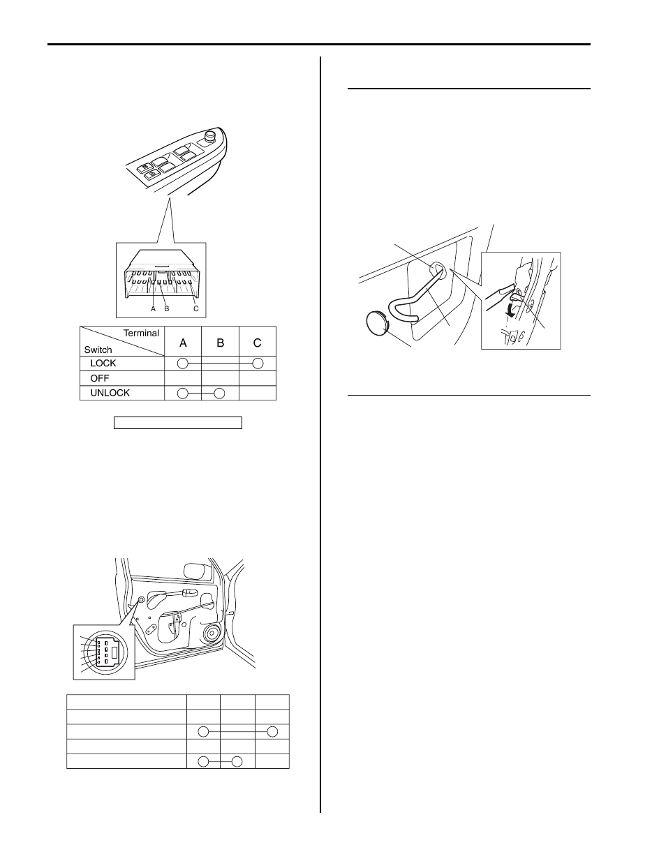
Power Door Lock Switch Inspection

S6JB0A9606004

Check for continuity between terminals at each switch 
position. If check result is not as specified, replace 
switch.

Door Key Cylinder Switch Inspection

S6JB0A9606005

1) Remove front door trim referring to Step 1) to 3) of 

“Front Door Glass Removal and Installation in 
Section 9E”

2) Check for continuity between terminals at each 

switch position. If check result is not as specified, 
replace door lock assembly.

Power Door Lock Actuator Inspection

S6JB0A9606006

NOTE
If rear end door is closed and the rear end 
door lock actuator does not function in 
unlock position, follows the procedures to 
unlock the rear end door lock actuator.
1. Remove cap (1).
2. Penetrate door sealing cover (2) by jack 

lever (3) or whatever to insert jack lever, 
and push emergency lever (4) into unlock 
position “a”.

3. After inspection replace door sealing 

cover.


1) Remove door trim from door panel.

For front door, refer to Step 1) to 3) of “Front Door 
Glass Removal and Installation in Section 9E”.
For rear door, refer to Step 1) to 3) of “Rear Door 
Glass Removal and Installation in Section 9E”.
For rear end door, refer to Step 1) of “Rear End Door 
Assembly Removal and Installation in Section 9J”.

2) Disconnect power door lock actuator coupler.
3) Connect battery positive (+) and negative (–) 

terminals to the door lock actuator terminals (a, b, c, 
d) as shown in figure.
If it does not operate as specified in the following 
table, replace door lock assembly.

1. Power door lock switch

I5JB0A960007-01

a

b

c

d

e

f

LOCK

OFF

UNLOCK

d

a

b

c

f

e

Right side switch terminals

Left side switch terminals

I5JB0A960008-01

2

3

1

4

“a”

I5JB0A960022-01

Security and Locks:  9F-8

For front door

For rear door

[A]: Without deadlock

[B]: With deadlock

[A]

[B]

a

b

c

d

e

f

Right side switch terminals

b

a

c

Lock

Unlock

Unlock

Lock

Deadlock

Unlock

Left side switch terminals

d

c

a

Deadlock

Lock

d

b

Lock

Unlock

f

e

Terminals

Lock

Unlock

Unlock

Lock

Terminals

d

a

Lock

Unlock

f

e

Terminals

I5JB0A960009-02

[A]: Without deadlock

[B]: With deadlock

[A]

[B]

a

b

c

d

e

f

g

h

Lock

Unlock

g

h

e

f

Right side switch terminals

Left side switch terminals

Right side switch terminals

d

c

a

Lock

Unlock

Unlock

Lock

Deadlock

Lock

Left side switch terminals

b

a

c

Deadlock

Lock

b

d

Lock

Unlock

Unlock

Lock

Terminals

d

a

Lock

Unlock

f

g

Terminals

I5JB0A960010-01

9F-9 Security and Locks: 

For rear end door

Rear Door Lock Assembly Components

S6JB0A9606007

Lock

Unlock

Unlock

Lock

Terminals

b

a

Lock

Unlock

c

d

Terminals

b

a

c

d

I5JB0A960011-02

(a)

(a)

(a)

(b)

1

7

2

6

3

4

5

I5JB0A960012-03

1. Outside handle

: Apply lithium grease 99000-25011 to sliding part.

4. Latch striker

7. Out side handle cap

2. Outside handle frame

: Apply lithium grease 99000-25011 to sliding part and spring.

5. Shim

: 5.0 N

⋅m (0.5 kgf-m, 4.0 lb-ft)

3. Rear door latch assembly 

: Apply lithium grease 99000-25011 to sliding part.

6. Inside handle bezel

: 10 N

⋅m (1.0 kgf-m, 7.5 lb-ft)

Security and Locks:  9F-10

Rear Door Lock Assembly Removal and 
Installation

S6JB0A9606008

Removal

1) Remove rear door trim referring to step 1) to 3) of 

“Rear Door Glass Removal and Installation in 
Section 9E”
.

2) Disconnect door lock motor lead wire.
3) Remove door latch mounting screws (1) and remove 

door latch assembly (2).

Installation
Reverse removal procedure to install rear door lock 
assembly referring to the following instruction and “Front 
Door Lock Assembly Removal and Installation”.
• Tighten door latch screw to specified torque.

Tightening torque
Door latch screw (a):  5.0 N·m (0.5 kgf-m, 4.0 lb-ft)

Rear Door Lock Assembly Inspection

S6JB0A9606009

• Check that door opens and closes smoothly and 

properly.

• Check that door stops in the secondary latched 

position properly (preventing door from opening 
freely) and that door closes completely in the fully 
latched position.

• Adjust door latch striker position, if necessary.

1

2

I6JB0A960002-01

(a)

I5JB0A960014-01


Content   ..  503  504  505  506   ..