Suzuki Grand Vitara JB416 / JB420 / JB419. Service manual - part 486
 

  Index      Suzuki     Suzuki Grand Vitara JB416 / JB420 / JB419 - service and repair manual 2007 year


Search            copyright infringement  


Content   ..  484  485  486  487   ..


Suzuki Grand Vitara JB416 / JB420 / JB419. Service manual - part 486


9B-29 Lighting Systems: 

Headlight Manual Leveling Switch Inspection (If 
Equipped)

S6JB0A9206022

Check for continuity between terminals at each switch 
position.
If check result is not as specified, replace switch.

Headlight Leveling Actuator Inspection (If 
Equipped)

S6JB0A9206023

Vehicle equipped with headlight auto leveling 
system

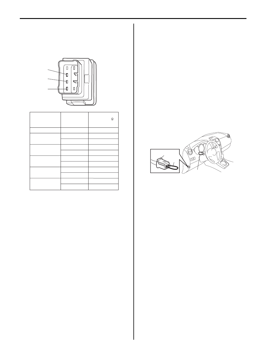
1) Make sure all couplers of headlight and leveling 

actuator are connected securely.

2) Park vehicle in front of blank wall (screen).
3) Turn ignition switch to ON position.
4) Perform “Headlight Leveling Warning Light Check”.
5) Connect service wire (2) to terminals of diagnosis 

connector (1).

6)  Perform Steps a) through c) described below within 

20 seconds after Step 5).
a) Turn lighting switch (3) to “HEAD” position and 

then turn lighting switch to OFF position.

b) Repeat Step a) 2 times.
c) Turn lighting switch (3) to “HEAD” position.

7) Check that optical axes of headlights reflected on 

blank wall (screen) change. If not, go to “Headlight 
Auto Leveling System Symptom Diagnosis (If 
Equipped)”. 

Vehicle equipped with manual leveling headlight 
system

1) Make sure all couplers of headlight and leveling 

actuator are connected securely.

2) Park vehicle in front of blank wall (screen).
3) Turn ignition switch to ON position.
4) Turn lighting switch to “HEAD” position.
5) Move headlight leveling switch and check that 

optical axes of headlights reflected on blank wall 
(screen) change then.Also check that leveling 
actuator sounds slightly while moving leveling 
switch. If optical axes do not change, go to 
“Headlight Manual Leveling System Symptom 
Diagnosis (If Equipped)”. 

1

2

3

Switch Position

0

Terminal

Resistance (   )

-

1

2

3

4

1 and 2

4370 - 4830

1 and 3

2 and 3

1 and 3

2 and 3

1 and 3

2 and 3

1 and 3

2 and 3

1 and 3

2 and 3

646 - 714

3724 - 4116

3078 - 3402

1292 - 1428

1938 - 2142

2584 - 2856

3230 - 3570

2432 - 2688

1786 - 1974

1140 - 1260

I4RS0B920012-01

1

2

3

I5JB0A920032-01

Lighting Systems:  9B-30

Rear Fog Light Switch Inspection (If Equipped)

S6JB0A9206024

NOTE

• Rear fog light switch can be turned to ON 

position only when headlight switch is 
turned to HEADLIGHT position (low or high 
beams).

• Rear fog light switch turns OFF 

automatically when headlight switch is 
turned to OFF position.


Check for continuity between terminals at each switch 
position.
If check result is not as specified, replace switch.

Height Sensor Removal and Installation (If 
Equipped)

S6JB0A9206025

Removal

CAUTION

!


• Do not remove bracket (4) and link (3) from 

height sensor (2). Removal will spoil its 
original function. If faulty condition is 
found, replace it with new one in a set.

• If height sensor was dropped from a height 

of 30 cm (0.9 ft) or more, replace it with 
new one.


1) Disconnect negative (–) cable at battery.
2) Disconnect height sensor connector (1) from height 

sensor (2).

3) Remove front height sensor with its bracket (4) from 

suspension frame (6) and lower arm (5).

Terminal

Shaft condition

1

2

OFF

ON

ON

OFF

2

1

I4RS0B920013-01

[A]: Front

[B]: Rear

6

1

3

2

4

[B]

1

3

4

6

2

5

[A]

5

4

4

I5JB0A920033-02

9B-31 Lighting Systems: 

Installation
For installation, reverse removal procedure noting the 
following.
• Check that bracket and link of height sensor are not 

deformed.

• Tighten height sensor bolts and nuts to specified 

torque.

Tightening torque
Height sensor bolt (a):  10 N·m (1.0 kgf-m, 7.5 lb-
ft)
Height sensor nut (b):  10 N·m (1.0 kgf-m, 7.5 lb-ft)

• Connect connector securely.
• After installation, initialize auto leveling headlight 

system referring to “Initialization of Auto Leveling 
Headlight System”.

Height Sensor and Its Circuit Inspection (If 
Equipped)

S6JB0A9206026

1) Remove front or rear height sensor from vehicle 

referring to “Height Sensor Removal and Installation 
(If Equipped)”
.

2) Connect connector to height sensor.
3) Vary position of height sensor link (1) and measure 

voltage between terminals of headlight auto leveling 
control module (4) as described below.
• For front height sensor 

Between “G51-20” and “G51-22” terminals of 
headlight leveling control module.

• For rear height sensor

Between “G51-19” and “G51-21” terminals of 
headlight leveling control module.
If check result is not as specified, perform 
inspections of power supply, ground and signal 
circuits of front or rear height sensor which is 
described under “Inspection of Headlight Leveling 
Control Module and Its Circuit (Vehicle Equipped 
With Auto Leveling Headlight System)”.
 If circuits 
are OK, replace height sensor.

Height sensor output voltage
Full bound position (2): about 0.5 V
Full rebound position (3): about 4.5 V

[A]: Front

[B]: Rear

[B]

[A]

(a)

(b)

(a)

(b)

I5JB0A920040-01

[A]: Front

[B]: Rear

G51

10

11

12

13

16

17

18

19

20

3

1

5

6

9

21

22

23

24

V

[A]

[B]

1

3

2

3

2

1

4

I5JB0A920034-02

Lighting Systems:  9B-32

Headlight Leveling Control Module Removal 
and Installation (If Equipped)

S6JB0A9206027

Removal

1) Disconnect negative (–) cable at battery.
2) Disconnect connector (1) from headlight leveling 

control module (2).

3) Remove headlight leveling control module with its 

bracket from heater unit (3).

Installation
For installation, reverse removal procedure noting the 
following.
• Connect connector securely.
• After replacing headlight leveling control module with 

new one, initialize auto leveling headlight system 
referring to “Initialization of Auto Leveling Headlight 
System”.

Initialization of Auto Leveling Headlight System

S6JB0A9206028

Initialization of the auto leveling headlight system is to 
make the headlight leveling control module learn signals 
which are fed from the height sensors when the vehicle 
is at the standard height. Standard height means the 
height of the vehicle with a driver but without load in it. 
Initialization of the auto leveling headlight system is 
required when any of the following works has been 
performed.
• Replacement of headlight leveling control module
• Removal of front and/or rear height sensor link from 

lower arm

• Removal of front and/or rear height sensor from 

suspension frame

•  Replacement of front and/or rear height sensor

Without initialization of the auto leveling headlight 
system, it is not possible to obtain its proper function. 
Also, if the auto leveling headlight system is not 
initialized after replacing the headlight leveling control 
module, the headlight leveling warning light in the 
combination meter flashes.

1) Observe the following instructions.

•  Park vehicle on level ground.
• Adjust air pressure of all tires to the specified 

value respectively.

• Bounce vehicle body up and down by hand to 

stabilize suspension.

2) Turn ignition switch to ON position.
3) Perform “Headlight Leveling Warning Light Check”.
4) Connect service wire (2) to terminals of diagnosis 

connector (1).

5) Perform Steps a) through b) described blow within 

20 seconds after Step 4).
a) Turn lighting switch (3) to “HEAD” position and 

then turn lighting switch to OFF position.

b) Repeat Step a) 2 times.

6)  Confirm that headlight leveling warning light flashes 

3 times and turns off, which indicates that system 
initialization was completed properly. If it does not 
turn off after flashing 3 times, it means initialization 
was not successful. In such case, turn off ignition 
switch and perform Steps 1) to 6) again.

1

3

2

I5JB0A920035-01

1

2

3

I5JB0A920032-01

1

I5JB0A920012-02


Content   ..  484  485  486  487   ..