Suzuki Grand Vitara JB416 / JB420 / JB419. Service manual - part 420
 

  Index      Suzuki     Suzuki Grand Vitara JB416 / JB420 / JB419 - service and repair manual 2007 year


Search            copyright infringement  


Content   ..  418  419  420  421   ..


Suzuki Grand Vitara JB416 / JB420 / JB419. Service manual - part 420


8B-65 Air Bag System: 

NOTE
Upon completion of inspection and repair work, perform the following items.
• Reconnect all air bag system components and ensure all components are properly mounted.
• Clear DTCs referring to “DTC Clearance”,
 if any.
• Repeat “Air Bag Diagnostic System Check” 
to confirm that the trouble has been corrected.


3

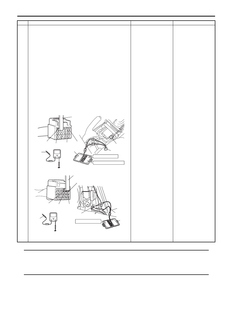
1) With ignition switch OFF, disconnect special tools (A), 

(B) and (C) or (D) and SDM connector “G47” or “L33”.

2) Release shorting bar in SDM connector inserting release 

tool (1) included in special tool (A).

3) Measure voltage between “G47-7” and body ground, 

“G47-8” and body ground (for DTC B1053) or “G47-1” 
and body ground, “G47-2” and body ground (for DTC 
B1057) [A], or between “L33-5” and body ground, “L33-
6” and body ground (for DTC B1053) or “L33-7” and 
body ground, “L33-8” and body ground (for DTC B1057) 
[B].

Special tool
(A):  09932–76010 
(B):  09932–75010 
(C):  09932–78310 
(D):  09932–77320 

With ignition switch ON, is voltage 4 V or less?

Substitute a known-
good SDM and recheck.

DTC B1054: “GRN/
ORN” circuit or “GRN/
YEL” circuit shorted to 
power supply circuit. 
(Between “G55” and 
“G47” connectors or 
between “L12” and 
“L33” connectors)
DTC B1058: “BLU/
ORN” circuit or “BLU/
YEL” circuit shorted to 
power supply circuit. 
(Between “G55” and 
“G47” connectors or 
between “L36” and 
“L33” connectors)

Step

Action

Yes

No

BASE OF COLUMN

PASSENGER INFLATOR

[A]

“L12”, “L36”

[B]

(C)

(B)

(A)

STEERING WHEEL

(A)

1, (A)

(A)

(B)

(D)

1, (A)

“G47-1”

“G47-2”

“G47-7” “G47-8”

“L33-8”

“L33-5”

“L33-6”

“L33-7”

“G55”

I5JB0A820043-01

Air Bag System:  8B-66

DTC B1073 / B1077: Driver / Passenger Forward-Sensor Circuit Short to Ground

S6JB0A8204027

Wiring Diagram

CAUTION

!


Be sure to observe instructions under CAUTION in “Air Bag Diagnostic System Check Flow”.


DTC Will Set when
Forward-sensor abnormal signal is detected by SDM.

Flow Test Description
Step 1: Check for short circuit between forward-sensor circuit and ground.
Step 2: Check if malfunction is in forward-sensor.

5V

BLK

G47-20 GND

“G47”

1

2

4

3

RED

BLK/YEL

“G01”

G47-16

IG

[A]

G47-19

G47-11

FP+

FP-

G47-17

G47-9

FD+

FD-

“G47”

ORN

PNK/BLK

ORN

PNK/BLK

“E77”

“G06”

“E24”

“E13”

PNK

PNK/BLU

PNK

PNK/BLU

BLK

G46-16 GND

“G46”

1

2

4

3

RED

BLK/YEL

“G01”

G46-11

IG

[B]

L33-11

L33-12

FP+

FP-

L33-10

L33-9

FD+

FD-

5V

ORN

PNK/BLK

ORN

PNK/BLK

“E79”

“L03”

“E24”

“E13”

PNK

PNK/BLU

PNK

PNK/BLU

“L33”

8

8

5

5

6

6

7

7

I5JB0A820049-01

[A]: Without side-air bag and curtain-air bag

3. “A/B” fuse

7. Passenger forward-sensor

[B]: With side-air bag and curtain-air bag

4. Junction block assembly

8. Ground for air bag system

1. From main fuse

5. SDM

2. Ignition switch

6. Forward-sensor

8B-67 Air Bag System: 

DTC Troubleshooting

NOTE
Upon completion of inspection and repair work, perform the following items.
• Reconnect all air bag system components and ensure all components are properly mounted.
• Clear DTCs referring to “DTC Clearance”,
 if any.
• Repeat “Air Bag Diagnostic System Check” 
to confirm that the trouble has been corrected.


Step

Action

Yes

No

1

1) Turn ignition switch to OFF position.
2) Disconnect forward-sensor connector “E13” or “E24”.
3) Disconnect SDM connector “G47” or “L33”.
4) Check proper connection to SDM connector at terminals 

“G47-9” and “G47-17” or “L33-9” and “L33-10” (for DTC 
B1073) or terminals “G47-11” and “G47-19” or “L33-11” 
and “L33-12” (for DTC B1077).

5) Measure resistance between “G47-9” and body ground, 

“G47-17” and body ground (for DTC B1073) or “G47-11” 
and body ground, “G47-19” and body ground (for DTC 
B1077) [A], or between “L33-9” and body ground, “L33-
10” and body ground (for DTC B1073) or “L33-11” and 
body ground, “L33-12” and body ground (for DTC 
B1077) [B].

Special tool
(A):  09932–76010

Is each measured resistance infinity?

Go to Step 2.

For DTC B1073: “ORN” 
circuit or “PNK/BLK” 
circuit shorted to 
ground.
For DTC B1077: “PNK” 
circuit or “PNK/BLU” 
circuit shorted to 
ground.

2

1) Check forward-sensor referring to “Forward-Sensor 

Inspection”.

Is it in good condition?

Substitute a known-
good SDM and recheck.

Replace forward-sensor 
referring to “Forward-
Sensor Removal and 
Installation”. If DTC 
still 
exists, substitute a 
known-good SDM and 
recheck.

[A]

[B]

“G47-17”

“G47-9”

“G47-19” “G47-11”

“L33-10”

“L33-9”

“L33-11” “L33-12”

(A)

I5JB0A820050-02

Air Bag System:  8B-68

DTC B1074 / B1078: Driver / Passenger Forward-Sensor Circuit Short to Power Circuit or Open

S6JB0A8204028

Wiring Diagram
Refer to “DTC B1073 / B1077: Driver / Passenger Forward-Sensor Circuit Short to Ground”.

CAUTION

!


Be sure to observe instructions under CAUTION in “Air Bag Diagnostic System Check Flow”.


DTC Will Set when
Forward-sensor abnormal signal is detected by SDM.

Flow Test Description
Step 1: Check for open circuit in forward-sensor circuit.
Step 2: Check for short circuit between forward-sensor circuit and power supply circuit.
Step 3: Check if malfunction is in forward-sensor.

DTC Troubleshooting

Step

Action

Yes

No

1

1) Turn ignition switch to OFF position.
2) Disconnect forward-sensor connector “E13” or “E24”.
3) Disconnect SDM connector “G47” or “L33”.
4) Check proper connection to SDM connector at terminals 

“G47-9” and “G47-17” or “L33-9” and “L33-10” (for DTC 
B1074), or terminals “G47-11” and “G47-19” or “L33-11” 
and “L33-12” (for DTC B1078).

5) Check proper connection to forward-sensor connector at 

terminals “E13-1” and “E13-2” or “E24-1” and “E24-2”.

6) Using service wire (1), connect “E13-1” and “E13-2” 

terminal (for DTC B1074) or “E24-1” and “E24-2” 
terminal (for DTC B1078) of forward-sensor connector.

7) Measure resistance between “G47-9” and “G47-17” (for 

DTC B1074) or “G47-11” and “G47-19” (for DTC B1078) 
[A], or between “L33-9” and “L33-10” (for DTC B1074) or 
“L33-11” and “L33-12” (for DTC B1078) [B].

Special tool
(A):  09932–76010 

Is each measured resistance 1 

 or less?

Go to Step 2.

For DTC B1074: High 
resistance or open wire 
in “ORN” circuit or 
“PNK/BLK” circuit.
For DTC B1078: High 
resistance or open wire 
in “PNK” circuit or “PNK/
BLU” circuit.

“E13-1”, “E24-1”

“E13-2”, “E24-2”

1

[A]

[B]

“L33-12”

“L33-9” “L33-10” “L33-11”

“G47-9” “G47-17” “G47-19” “G47-11”

(A)

I5JB0A820051-01


Content   ..  418  419  420  421   ..