Suzuki Grand Vitara JB416 / JB420 / JB419. Service manual - part 399
 

  Index      Suzuki     Suzuki Grand Vitara JB416 / JB420 / JB419 - service and repair manual 2007 year


Search            copyright infringement  


Content   ..  397  398  399  400   ..


Suzuki Grand Vitara JB416 / JB420 / JB419. Service manual - part 399


7B-87 Air Conditioning System: 

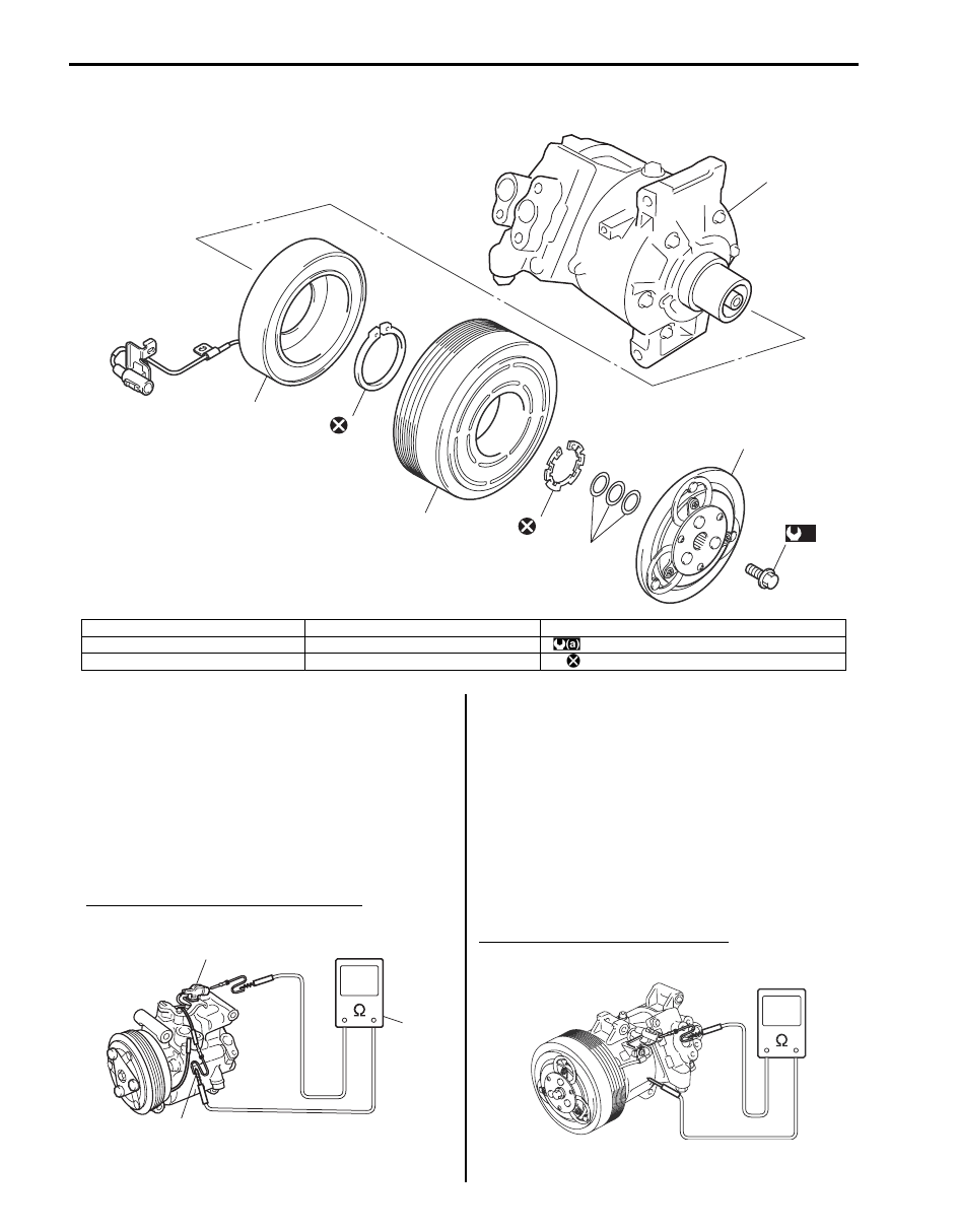
Magnet Clutch Components (F9Q Engine Model)

S6JB0A7206050

Magnet Clutch Operating Check for M16 Engine 
Model

S6JB0A7206038

Check the following items.
• Inspect armature plate and rotor for signs of oil.
• Check clutch bearings for noise and grease leakage.
• Using an ohmmeter (3), measure resistance of stator 

coil between clutch lead wire (1) and body ground (2). 
If measured resistance is not within tolerance, replace 
coil.

Standard resistance for magnet clutch
Approx. 2.9 – 3.2 

 at 20 °C (68 °F)

Magnet Clutch Operating Check for J20 Engine 
Model

S6JB0A7206039

Check the following items.
If any detects are found, repair or replace magnet clutch 
assembly.
• Inspect armature plate and rotor for signs of oil.
• Check clutch bearings for noise and grease leakage.
• Using an ohmmeter (3), measure resistance of stator 

coil between clutch lead wire (1) and body ground (2). 
If measured resistance is not within tolerance, replace 
coil.

Specified current of magnet clutch
Approx. 3.8 – 6.0 

 at 25 °C (77 °F)

2

7

3

5

6

1

4

4

(a)

I5JB0B720018-02

1. Armature plate bolt

4. Circlip

7. Compressor body assembly

2. Armature plate

5. Magnet clutch pulley

: 21 N

⋅m (2.1 kgf-m, 15.5 lb-ft)

3. Shim(s)

6. Magnet clutch coil

: Do not reuse.

1

2

3

I5JB0A720062-01

I5JB0A720063-02

Air Conditioning System:  7B-88

Magnet Clutch Operating Check (F9Q Engine 
Model)

S6JB0A7206051

Check the following items.
If any detects are found, repair or replace magnet clutch 
assembly.
• Inspect armature plate and rotor for signs of oil.
• Check clutch bearings for noise and grease leakage.
• Using an ohmmeter (3), measure resistance of stator 

coil between clutch lead wire (1) and body ground (2). 
If measured resistance is not within tolerance, replace 
coil.

Specified current of magnet clutch
Approx. 3.8 – 6.0 

 at 25 °C (77 °F)

Magnet Clutch Removal and Installation for M16 
Engine Model

S6JB0A7206040

Removal

1) Remove compressor from vehicle. Refer to 

“Compressor Assembly Removal and Installation for 
M16 Engine Model”.

2) Fix armature plate (1) with special tool (A) and 

remove armature plate bolt (2).

Special tool
(A):  09991–06310

NOTE
Do not reuse armature plate bolt.


3) Remove armature plate.
4) Remove shims from shaft.
5) Using special tool (A), remove circlip (1).

Special tool
(A):  09900–06107

6) Remove magnet clutch lead wire clamp screw, and 

remove magnet clutch read wire ground terminal.

7) Remove magnet clutch pulley with puller (1).

NOTE
Be careful not to damage pulley when 
tapping magnet clutch.


8) Remove magnet clutch bolts, and then remove 

magnet clutch coil.

NOTE
Do not reuse magnet clutch bolts.


3

1

2

I5JB0B720022-02

1

2

(A)

I5JB0A720064-02

2. Compressor

(A)

1

I5JB0A720065-01

1

2

I5JB0A720066-01

7B-89 Air Conditioning System: 

Installation

1) Install magnet clutch coil (2), and then tighten new 

magnet clutch coil bolts (1) as specified torque.

Tightening torque
Magnet clutch coil bolt (a):  4.9 N·m (0.49 kgf-m, 
4.0 lb-ft)

2) Install clamp portion and ground terminal of lead 

wire.

3) Install magnet clutch pulley (1).

a) Set magnet clutch squarely over clutch 

installation boss.

b) Place special tool (A) onto clutch bearing.

Ensure that edge rests only on inner race of 
bearing.

Special tool
(A):  09951–15510

c) Install snap ring (1) using special tool (B).

Special tool
(B):  09900–06107

CAUTION

!


Be careful not to scratch bearing seal.


4) Inspect clearance between armature plate (1) and 

magnet clutch pulley as follows.
a) Put compressor in a vise (2).
b) Set dial gauge (3) on armature plate, and then 

adjust its pointer at 0.

c) Connect battery positive terminal (+) to magnet 

clutch coil lead wire.

d) Connect battery negative terminal (–) to 

compressor body assembly. (At this point, 
armature plate and magnet clutch pulley are kept 
in contact.)

e) Disconnect battery negative terminal (–) to 

compressor body assembly. (At this point, 
armature plate and magnet clutch pulley are not 
in contact.)

f) Read stroke of armature plate from dial gauge by 

performing Step d) and e) repeatedly. (Stroke of 
armature plate is clearance between armature 
plate and magnet clutch pulley.)
If clearance is out of specification, adjust 
clearance by changing number and/or thickness 
of shim(s).

Standard clearance between armature plate and 
magnet clutch
“a”: 0.3 – 0.5 mm (0.012 – 0.020 in.)

2

1, (a)

I5JB0A720067-02

1

(A)

I5JB0A720068-02

(B)

1

1

I5JB0A720087-02

1

2

1

3

“a”

I5JB0A720069-01

Air Conditioning System:  7B-90

5) Tighten new armature plate bolt (1) as specified 

torque.

Tightening torque
Armature plate bolt (a):  15 N·m (1.5 kgf-m, 11.0 
lb-ft)

Special tool
(A):  09991–06310

Magnet Clutch Removal and Installation for J20 
Engine Model

S6JB0A7206041

Removal

1) Remove compressor from vehicle referring to 

“Compressor Assembly Removal and Installation for 
J20 Engine Model”.

2) Fix armature plate (1) with special tool (A) and 

remove armature plate bolt.

Special tool
(A):  09991–06310

NOTE
Do not reuse armature plate bolt.


3) Remove armature plate.
4) Remove shim(s) from shaft.
5) Using special tool (A), remove snap ring (1).

Special tool
(A):  09900–06107

6) Remove magnet clutch pulley (1) with puller (2).

NOTE
Be careful not to damage pulley.


7) Remove snap ring (1) using special tool (B), and 

then remove magnet clutch coil (1).

Special tool
(A):  09900–06107

2. Armature plate

2

1

(A)

I5JB0A720070-02

1

(A)

2

I5JB0A720071-01

(A)

1

I5JB0A720072-01

1

2

I5JB0A720073-01

(A)

1

I5JB0A720074-02


Content   ..  397  398  399  400   ..