Suzuki Grand Vitara JB416 / JB420 / JB419. Service manual - part 395
 

  Index      Suzuki     Suzuki Grand Vitara JB416 / JB420 / JB419 - service and repair manual 2007 year


Search            copyright infringement  


Content   ..  393  394  395  396   ..


Suzuki Grand Vitara JB416 / JB420 / JB419. Service manual - part 395


7B-71 Air Conditioning System: 

A/C Condenser Assembly On-Vehicle 
Inspection

S6JB0A7206002

CAUTION

!


Be careful not to damage condenser fins. If 
condenser fin is bent, straighten it by using a 
screwdriver or pair of pliers. If any leakage is 
found from fitting or tube, repair or replace 
condenser.


NOTE
Clogged condenser fins should be washed 
with water, and should be dried with 
compressed air.


Check the followings.
• Clog of condenser fins.

If any clog is found, condenser fins should be washed 
with water and should be dried with compressed air.

• Condenser fins for leakage and breakage If any 

defects are found, repair or replace condenser.

• Condenser fittings for leakage. If any defects are 

found, repair or replace condenser.

A/C Condenser Assembly Removal and 
Installation

S6JB0A7206003

CAUTION

!


Do not damage condenser fins. If condenser 
fin is bent, straighten it by using flat head 
screwdriver or pair of pliers.


Removal

1) Disconnect negative (–) cable at battery.
2) Recover refrigerant from A/C system referring to 

“Operation Procedure for Charging A/C with 
Refrigerant”.

NOTE
The amount of removed compressor oil must 
be measured for replenishing compressor 
oil.


3) Remove front bumper assembly referring to “Front 

Bumper Components in Section 9K”.

4) Remove front bumper upper member referring to 

“Front Bumper Components in Section 9K”.

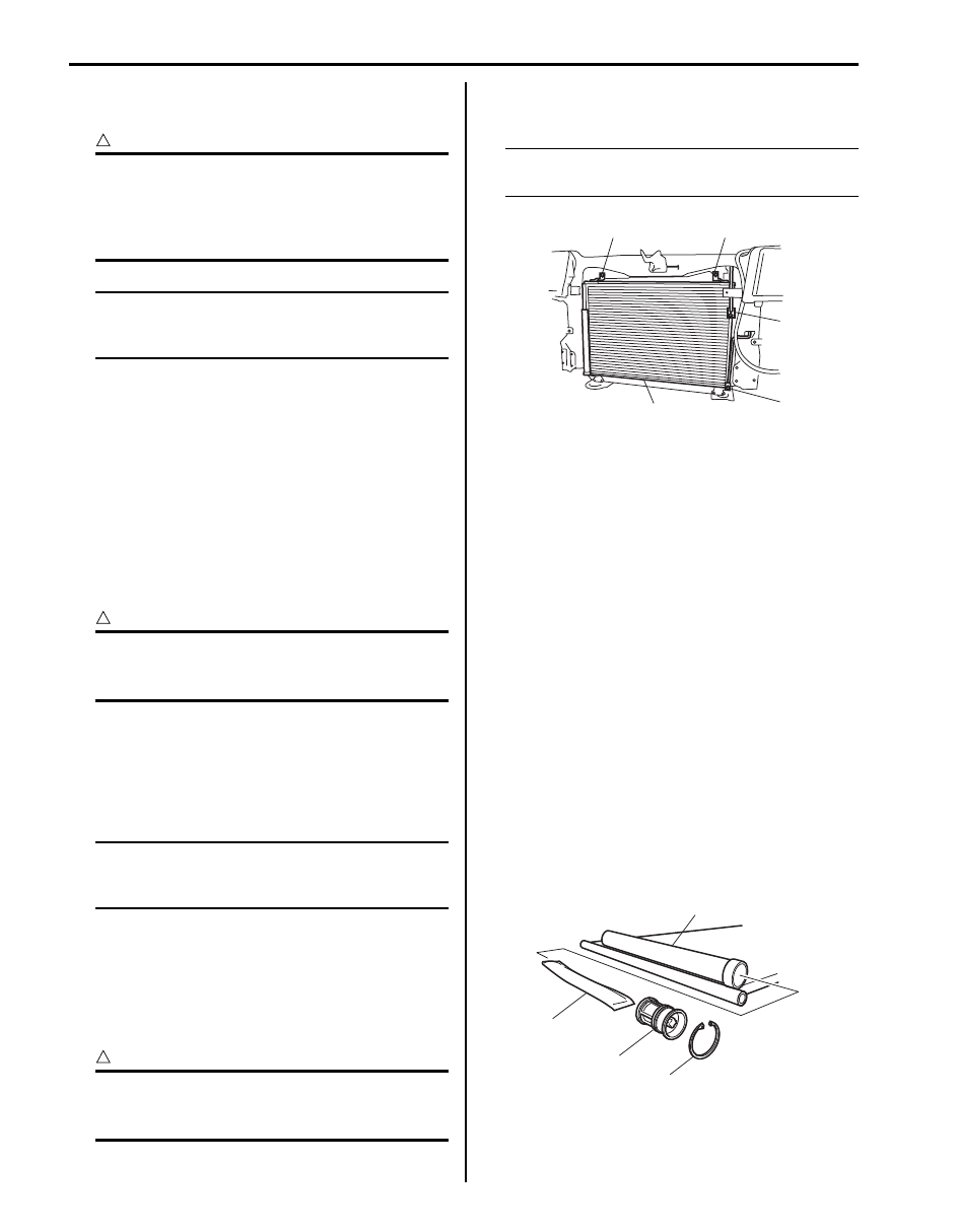
5) Disconnect compressor discharge hose (1) and 

liquid pipe (2) from condenser assembly (4).

CAUTION

!


As soon as above hose and pipe are 
disconnected, cap opened fittings so that 
moisture and dust do not enter condenser.


6) Remove condenser assembly mounting bolts (3), 

and then remove condenser assembly.

NOTE
Be careful not to damage fins of condenser 
and radiator.


Installation
Reverse removal sequence to install condenser, noting 
the following point.
• Replenish specified amount of compressor oil to 

compressor suction side referring to “Precautions on 
Replenishing Compressor Oil”.

• Evacuate and charge the A/C system referring to 

“Evacuation” and “Charge” in “Operation Procedure 
for Charging A/C with Refrigerant”.

Desiccant Removal and Installation

S6JB0A7206004

Removal

1) Remove condenser assembly from vehicle referring 

to “A/C Condenser Assembly Removal and 
Installation”.

2) Remove circlip (4) using special tool.

Special tool
:  09900–06107 

3) Remove the filter (1) from the receiver / dryer tank 

(2).

4) Remove desiccant (3).

3

3

1

2

4

I5JB0A720036-02

3

2

1

4

I5JB0A720037-02

Air Conditioning System:  7B-72

Installation
Reverse removal sequence to install desiccant, 
according to instruction manual with supply parts.

NOTE

• Replenish specified amount of compressor 

oil to compressor suction side referring to 
“Precautions on Replenishing Compressor 
Oil”
.

• Install circlip (1) as shown in figure.


HVAC Air Filter Removal and Installation

S6JB0A7206005

Removal

1) Disconnect negative (–) cable at battery.
2) Remove glove box.
3) Remove filter cover (1).

4) Pull out filter element (1).

Installation
Reverse removal procedure for installation noting the 
followings:
• Install filter (1) into blower unit by paying attention to 

direction of arrow on filter.

• Enable air bag system after installation of filter.

Refer to “Enabling Air Bag System in Section 8B”.

HVAC Air Filter Inspection

S6JB0A7206006

Check that filter is not excessively dirty, damage or oily, 
clean filter with compressed air from air outlet side of 
filter. If abnormality is found, replace filter with new one.

1

I5JB0A720038-01

1

I5JB0A720039-01

1

I5JB0A720040-03

1

I5JB0A720041-03

I5JB0A720092-02

7B-73 Air Conditioning System: 

HVAC Unit Components

S6JB0A7206007

20

19

21

25

16

17

22

22

18

3

2

1

5

23

24

16

15

26

26

26

27

26

4

6

14

1

7

9

13

12

10

8

11

I6JB01720012-01

1. Blower upper case

10. Blower lower case

19. Temperature control links

2. Air intake control actuator

11. Blower motor

20. Temperature control actuator

3. Air intake control links

12. Blower motor controller

21. Inside air temperature sensor

4. Air filter (if equipped)

13. Foot duct

22. Air flow control links

5. Air filter cover

14. Aspirator

23. Air flow control links cover

6. Air intake control door assembly

15. Heater core

24. Air flow control actuator

7. Expansion valve

16. Heater unit upper case

25. Aspirator hose

8. Evaporator

17. Temperature control door assembly

26. Packing

9. Evaporator temperature sensor

18. Air flow control door assembly

27. O-ring

Air Conditioning System:  7B-74

CAUTION

!


Be careful not to damage A/C evaporator fins. If A/C evaporator fin is bent, straighten it by using flat 
head screwdriver or pair of pliers.


HVAC Unit Removal and Installation

S6JB0A7206008

Removal

WARNING

!


Failure to follow the following procedure and 
WARNING may cause air bag deployment, 
personal injury, damage to parts, or air bag 
being unable to deploy.
• Never rest a steering column assembly on 

steering wheel with air bag (inflator) 
module face down and column vertical.

• When handling the air bag (inflator) 

modules (driver and passenger), be careful 
not to drop it or apply an impact to it. If an 
excessive impact was applied (e.g., 
dropped from a height of 91.4 cm (3 feet) or 
more, never attempt disassembly or repair 
but replace it with a new one.

• When grease, cleaning agent. Oil, water, 

etc. has got onto air bag (inflator) modules 
(driver and passenger), wipe off 
immediately with a dry cloth.


1) Disconnect negative (–) cable at battery.
2) Disable air bag system referring to “Disabling Air 

Bag System in Section 8B”.

3) Recover refrigerant from A/C system using recovery 

and recycling equipment referring to “Recovery” in 
“Operation Procedure for Charging A/C with 
Refrigerant”.

4) For petrol engine model, drain engine coolant and 

disconnect heater hoses (1) from HVAC unit.

5) For diesel engine model, drain engine coolant 

referring to “Cooling System Draining: For Diesel 
Engine Model in Section 1F”
, and then remove 
heater hoses (1) from HVAC unit as follows.
a) Release lock plate (3) completely in arrow 

direction.

b) Remove quick joint (2).

6) Disconnect suction hose (4) and condenser outlet 

hose (5) by removing attaching bolt (6).

7) Remove instrument panel referring to “Instrument 

Panel Removal and Installation in Section 9C”.

8) Disconnect rear duct from HVAC unit.
9) Detach wiring, connectors and clamps from HVAC 

unit.

10) Remove HVAC unit (1).

[A]: Petrol engine model
[B]: Diesel engine model

1

5

4

[A]

[B]

6

6

2

3

5

4

1

I6JB0A720010-02

1

I5JB0A720044-01


Content   ..  393  394  395  396   ..