Suzuki Grand Vitara JB416 / JB420 / JB419. Service manual - part 342
 

  Index      Suzuki     Suzuki Grand Vitara JB416 / JB420 / JB419 - service and repair manual 2007 year


Search            copyright infringement  


Content   ..  340  341  342  343   ..


Suzuki Grand Vitara JB416 / JB420 / JB419. Service manual - part 342


5B-15 Manual Transmission/Transaxle: For Petrol Engine Model

Gear Shift Lever Front Case Assembly 
Disassembly and Reassembly

S6JB0A5216015

Disassembly

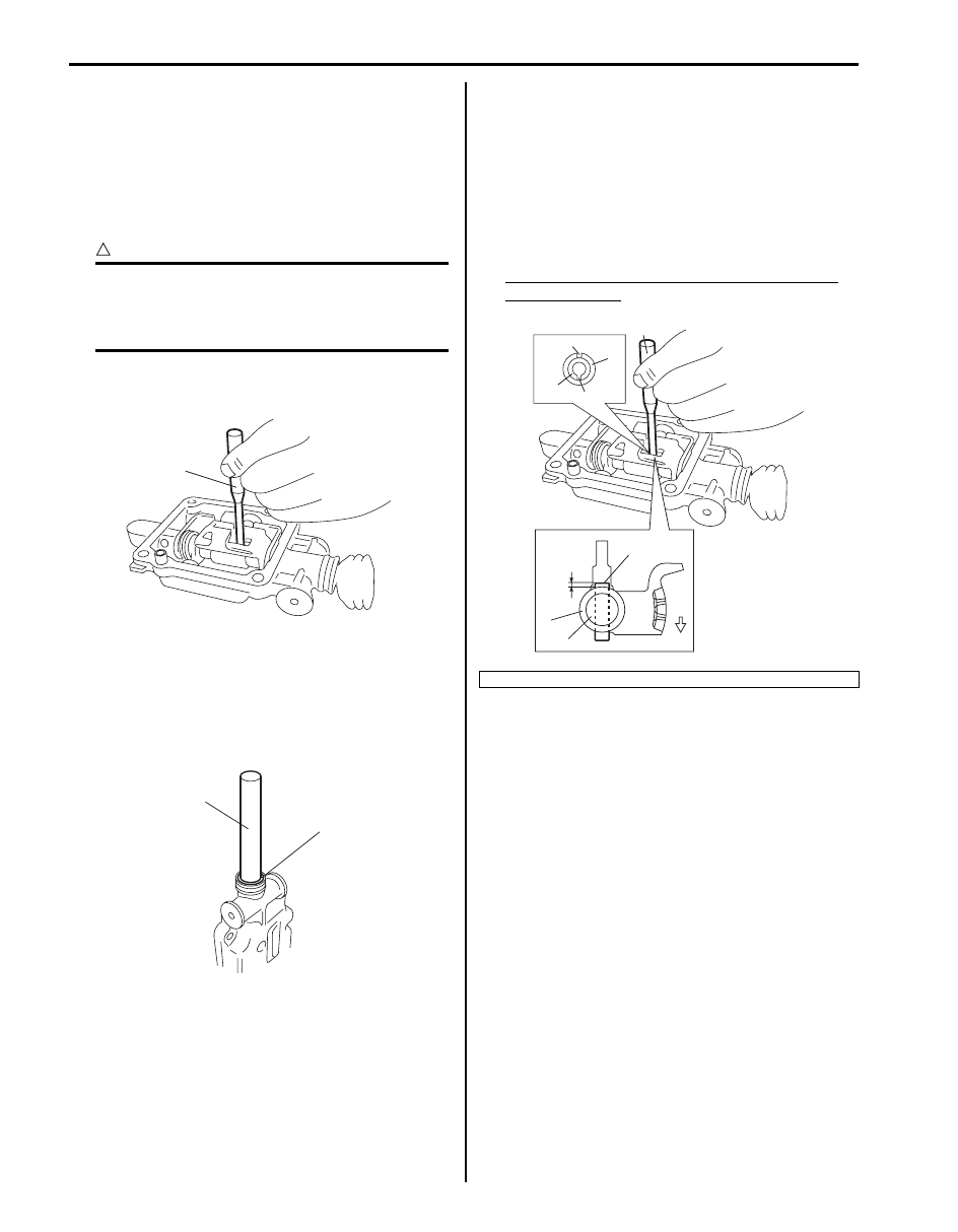
1) Remove gear shift case plug.
2) Drive out gear shift arm pin using special tool, and 

then disassemble components parts.

CAUTION

!


Be careful to disconnect gear shift shaft from 
gear shift lever front case so that gear shift 
locating ball and gear shift locating spring 
may be jumped out.


Special tool
(A):  09925–78210

Reassembly

1) Install new gear shift shaft oil seal (1) to gear shift 

lever front case using special tool.

Special tool
(A):  09923–46020

2) Assemble components parts referring to “Gear Shift 

Lever Front Case Assembly Components: For Petrol 
Engine Model”
.

3) Set new gear shift arm inner pin (1) and outer pin (2) 

facing each gap (“a”, “b”) as shown in figure.
Drive gear shift arm pins by using special tool, till pin 
protrusion becomes specified length “c”.

Special tool
(A):  09925–78210

Gear shift arm pin protrusion “c”: 0.5–1.5 mm 
(0.020–0.059 in.)

(A)

I5JB0A520012-01

1

(A)

I5JB0A520013-01

5. Case side

“a”

“b”

1

2

(A)

“c”

1, 2

3

4

5

I5JB0A520014-01

Manual Transmission/Transaxle: For Petrol Engine Model 5B-16

Gear Shift Lever Front Case Assembly 
Inspection

S6JB0A5216016

• Check that gear shift shaft moves smoothly without 

abnormal noise. If abnormality is found, replace 
defective part.

• Check bushes and boot for damage and deterioration. 

If abnormality is found, replace defective part.

Engine Rear Mounting Replacement

S6JB0A5216017

When replacement of mounting parts are necessary, 
torque bolts as specified below.

Tightening torque
Engine rear mounting No.1 bolt (a):  55 N·m (5.5 kgf-
m, 40.0 lb-ft)
Engine rear mounting member bolt (b):  55 N·m (5.5 
kgf-m, 40.0 lb-ft)
Engine rear mounting No.2 bolt (c):  55 N·m (5.5 kgf-
m, 40.0 lb-ft)

Manual Transmission Assembly Dismounting 
and Remounting

S6JB0A5216018

Dismounting

1) Disconnect negative (–) cable of battery.
2) Remove transmission shift control lever referring to 

“Transmission Shift Control Lever Removal and 
Installation: For Petrol Engine Model”
.

3) Detach engine harness clamps and ground wire 

harness from transmission front case.

4) Remove starting motor fastening bolts (2) and 

transmission fastening bolts (1).

5) Disconnect clutch fluid joint from pipe of clutch 

operating cylinder assembly referring to “Clutch 
Operating Cylinder Assembly Removal and 
Installation in Section 5C”.

6) Hoist vehicle.
7) Drain oil from transmission and transfer or extension 

case.

8) Remove propeller shafts referring to “Propeller Shaft 

Removal and Installation in Section 3D”.

9) Remove exhaust No. 2 pipe.

10) Remove engine under cover.

11) Remove clutch housing lower plates (1).

1. Engine rear mounting member
2. Engine rear mounting

I5JB0A520015-01

1

1

1

2

I5JB0A520016-01

5B-17 Manual Transmission/Transaxle: For Petrol Engine Model

12) Remove transmission fastening nut (2) and bolts (3).

13) Disconnect the following couplers and release their 

harness from clamps.
• Back up light switch
• Transfer shift actuator (if equipped)
• 4L/N switch (if equipped)
• Center differential lock switch (if equipped)

14) Apply transmission jack (1) and remove engine rear 

mounting member (2) taking off its bolts.

15) After removing mounting member, move rearward 

transmission and transfer or extension case 
assemblies placed on jack and then lower them.

16) Separate gear shift control lever rear case assembly 

(2) and transfer assembly (3) or extension case from 
transmission assembly (1).

Remounting
For remounting, reverse dismounting procedure.
• Apply grease to input shaft.

“A”:  Grease 99000–25010 (SUZUKI Super Grease 
A)

• Slant the rear of the engine down, using support 

device (1) and install transmission to engine.

2

1

1

3

3

I5JB0A520028-01

2

1

I5JB0A520029-01

2

1

3

I5JB0A520030-03

“A”

I5JB0A520031-01

I3JA01520024-01

Manual Transmission/Transaxle: For Petrol Engine Model 5B-18

• Use specified torques as given below.

Tightening torque
Transmission to engine bolt and nut (a):  85 N·m (
8.5 kgf-m, 61.5 lb-ft)
Engine rear mounting member bolt (b):  55 N·m (
5.5 kgf-m, 40.0 lb-ft)
Clutch housing lower plate bolt (c):  11 N·m (1.1 
kgf-m, 8.0 lb-ft)
Engine rear mounting No.2 bolt (d):  55 N·m (5.5 
kgf-m, 40.0 lb-ft)

• Set each clamp for wiring and hose securely.
• Install shift control lever referring to “Transmission 

Shift Control Lever Removal and Installation: For 
Petrol Engine Model”.

• Connect clutch fluid joint to pipe of clutch operating 

cylinder assembly referring to “Clutch Operating 
Cylinder Assembly Removal and Installation in 
Section 5C”.

• Install exhaust No.2 pipe referring to “Exhaust System 

Components: For Petrol Engine Model in Section 1K”.

• Fill gear oil to transmission referring to “Manual 

Transmission Oil Change: For Petrol Engine Model”.

• Fill gear oil to transfer or extension case referring to 

“Transfer Oil Change: Motor-Shift Type (Transfer with 
Shift Actuator) in Section 3C”, “
Transfer Oil Change: 
Non-Shift Type (Transfer without Shift Actuator) in 
Section 3C” 
or “Extension Case Oil Change: For 
Petrol Engine Model”.

• Connect battery and check function of engine, clutch, 

transmission and transfer.

• Install propeller shafts referring to “Propeller Shaft 

Removal and Installation in Section 3D”.

Manual Transmission Unit Disassembly

S6JB0A5216019

1) Remove clutch operating cylinder assembly from 

transmission front case referring to “Clutch 
Operating Cylinder Assembly Removal and 
Installation in Section 5C”

2) Remove gear shift control lever rear cause assembly 

and gear shift lever front case assembly referring to 
“Gear Shift Control Lever Rear Case Assembly 
Removal and Installation: For Petrol Engine Model” 
and “Gear Shift Lever Front Case Assembly 
Removal and Installation: For Petrol Engine Model”.

3) Separate transfer assembly (1) or extension case 

from transmission assembly.

4) Remove adapter case (1) from rear case (2).
5) Remove output shaft assembly (3) from adapter 

case.

6) Remove reverse shaft bolt (1) and back up light 

switch (2).

(a)

(a)

(a)

(c)

(c)

(b)

(b)

(d)

I5JB0A520032-01

1

I5JB0A520033-01

1

2

3

1

I5JB0A520034-01

2

1

I5JB0A520035-01


Content   ..  340  341  342  343   ..