Suzuki Grand Vitara JB416 / JB420 / JB419. Service manual - part 328
 

  Index      Suzuki     Suzuki Grand Vitara JB416 / JB420 / JB419 - service and repair manual 2007 year


Search            copyright infringement  


Content   ..  326  327  328  329   ..


Suzuki Grand Vitara JB416 / JB420 / JB419. Service manual - part 328


5A-103 Automatic Transmission/Transaxle: 

Automatic Transmission Assembly 
Dismounting and Remounting

S6JB0A5106028

Dismounting

1) Dismount engine with transmission and transfer 

referring to “Engine Assembly Removal and 
Installation: For J20 Engine in Section 1D”
.

2) Disconnect connectors from output shaft speed 

sensor, input shaft speed sensor, transmission range 
sensor, transmission wire, transfer actuator, 
differential lock switch and 4L/N (if equipped) switch 
release their wire harnesses from clamps.

3) Remove transfer (for 4WD model) or extension case 

assembly (for 2WD model) from transmission 
referring to “Transfer Assembly Dismounting and 
Remounting: Motor-Shift Type (Transfer with Shift 
Actuator) in Section 3C” (for
 4WD model) or 
“Extension Case Assembly Removal and 
Installation: For Petrol Engine Model in Section 5B” 
(for 2WD model).

4) Remove engine earth cable.
5) Remove engine rear mounting member and rear 

mounting referring to “Engine Mountings 
Components: For J20 Engine in Section 1D”.

6) Remove oil filler tube.
7) Remove cooler hose.
8) Remove drive plate cover, and then remove drive 

plate bolts by holding crankshaft pulley bolt 
stationary.

9) Remove Starting Motor referring to “Starting Motor 

Dismounting and Remounting: For Petrol Engine 
Model in Section 1I”.

10) Remove transmission assembly from engine 

assembly.

Installation
For remounting, reverse dismounting procedure noting 
the following points.
• Tighten each bolts and nuts referring to “Automatic 

Transmission Unit Components”

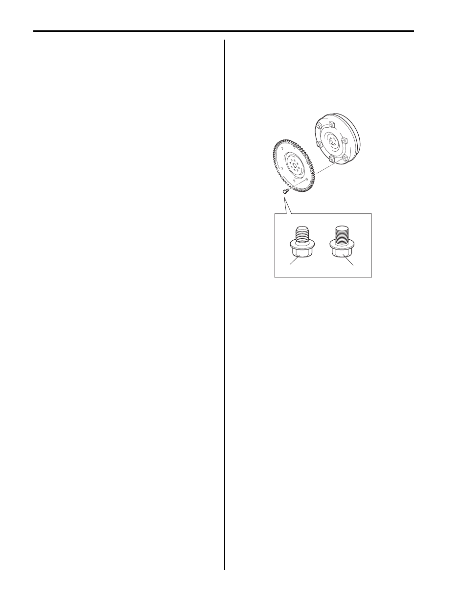
• Tighten drive plate bolt No.1 (1) first and then tighten 

drive plate bolts No.2 (2).

• Set each clamp for wiring securely.
• Fill A/T fluid referring to “A/T Fluid Change”.
• Connect battery and check function of engine and 

transmission.

1

2

I5JB0A510068-01

Automatic Transmission/Transaxle:  5A-104

Automatic Transmission Unit Disassembly

S6JB0A5106029

1) Extract torque converter. And remove oil filler tube 

and dipstick.

CAUTION

!


Remove torque converter as much straight 
as possible. Leaning it may cause damage to 
oil seal lip.


2) Remove input shaft speed sensor (1) and output 

shaft speed sensor (2).

3) Remove 6 adapter case fixing bolts and then remove 

adaptor case (3) and gasket.

NOTE
Use care not to cause damage to oil seal.


4) Remove shift switch (1).

5) Remove C-ring (1) and then remove speed sensor 

rotor (2).

NOTE
Use care not to loose rotor stop key.


6) Remove oil pump (1) by using special tools.

Special tool
(A):  09913–65135 
(B):  09927–66520 

NOTE
Use care not to cause damage to shaft 
bushing surface.


7) Remove bearing at the rear of oil pump (1).
8) Remove O-ring from oil pump (1).
9) Holding input shaft (2) by hand, remove converter 

housing (3).

1. Torque converter
2. Converter housing

1

2

I5JB0A510069-01

1

2

3

I5JB0A510070-02

1

I5JB0A510071-01

1

2

I5JB0A510072-01

3

(B)

(A)

2

1

I5JB0A510073-01

5A-105 Automatic Transmission/Transaxle: 

10) Check dimensions of overdrive (O/D) case (1) 

surface and clutch cylinder (2) surface for 
reassembly.

11) Remove overdrive (O/D) clutch assembly by holding 

input shaft (3).

12) Remove O/D case, bearing and bearing race.

NOTE
Confirm direction of bearing and bearing 
race for reassembly.


13) Remove oil pan (1).

NOTE

• Hold oil pan with oil pan side down to 

prevent foreign material in oil pan from 
entering valve body.

• If iron powder is found, it is possible that 

bearing, gear or clutch plate is worn.


14) Remove oil strainer (1).

15) Remove overdrive (O/D) brake apply tube (1).
16) Disconnect couplers, and then remove transmission 

wire connector (2).

17) Remove valve body (1) mounting bolts as shown in 

the figure.

18) Remove accumulator pistons (1) by blowing air into 

holes (2) as shown in the figure.

NOTE
Hold accumulator piston (1) with shop cloth 
while blowing.


1

2

3

2

1

I5JB0A510074-01

IYSQ01510094-01

1

I5JB0A510075-01

1

2

I5JB0A510077-02

1

I5JB0A510076-01

1

2

I5JB0A510078-04

Automatic Transmission/Transaxle:  5A-106

19) Place transmission (1) upright as shown in the 

figure.

NOTE

• To prevent transmission case from getting 

damaged, protect its contacting surface 
with stand by using shop cloth or the like.

• A stand of such size as shown in the figure 

will facilitate work.


20) Check top surface level of forward clutch (2) against 

case (1) for reassembly.

21) Remove forward clutch.

NOTE
Confirm direction of bearing and bearing 
race for reassembly.


22) Remove direct clutch (1).

23) Remove pawl bracket (1), and then parking lock rod 

(2) from manual shift lever.

24) Remove pawl spring (3), pawl pin and parking rock 

pawl (4).

25) Remove 2 bolts (1) from valve body side.

26) Remove center support assembly (1).

27) Remove retaining ring (1), planetary gear assembly 

leaf spring, bearing and bearing race.

NOTE

• Use care not to cause damage to case 

when removing retaining ring.

• Confirm direction of bearing and bearing 

race for reassembly.


A: 50 mm (1.9 in.)
B: 350 mm (13.8 in.)

C: 400 mm (15.7 in.)
D: 200 mm (7.9 in.)

1

C

A

D

B

I5JB0A510079-01

2

2

1

1

I5JB0A510080-01

1

I5JB0A510081-01

4

3

2

1

I5JB0A510082-01

1

I5JB0A510083-01

IYSQ01510104-01

1

I5JB0A510084-01


Content   ..  326  327  328  329   ..