Suzuki Grand Vitara JB416 / JB420 / JB419. Service manual - part 297
 

  Index      Suzuki     Suzuki Grand Vitara JB416 / JB420 / JB419 - service and repair manual 2007 year


Search            copyright infringement  


Content   ..  295  296  297  298   ..


Suzuki Grand Vitara JB416 / JB420 / JB419. Service manual - part 297


4F-36 Electronic Stability Program: 

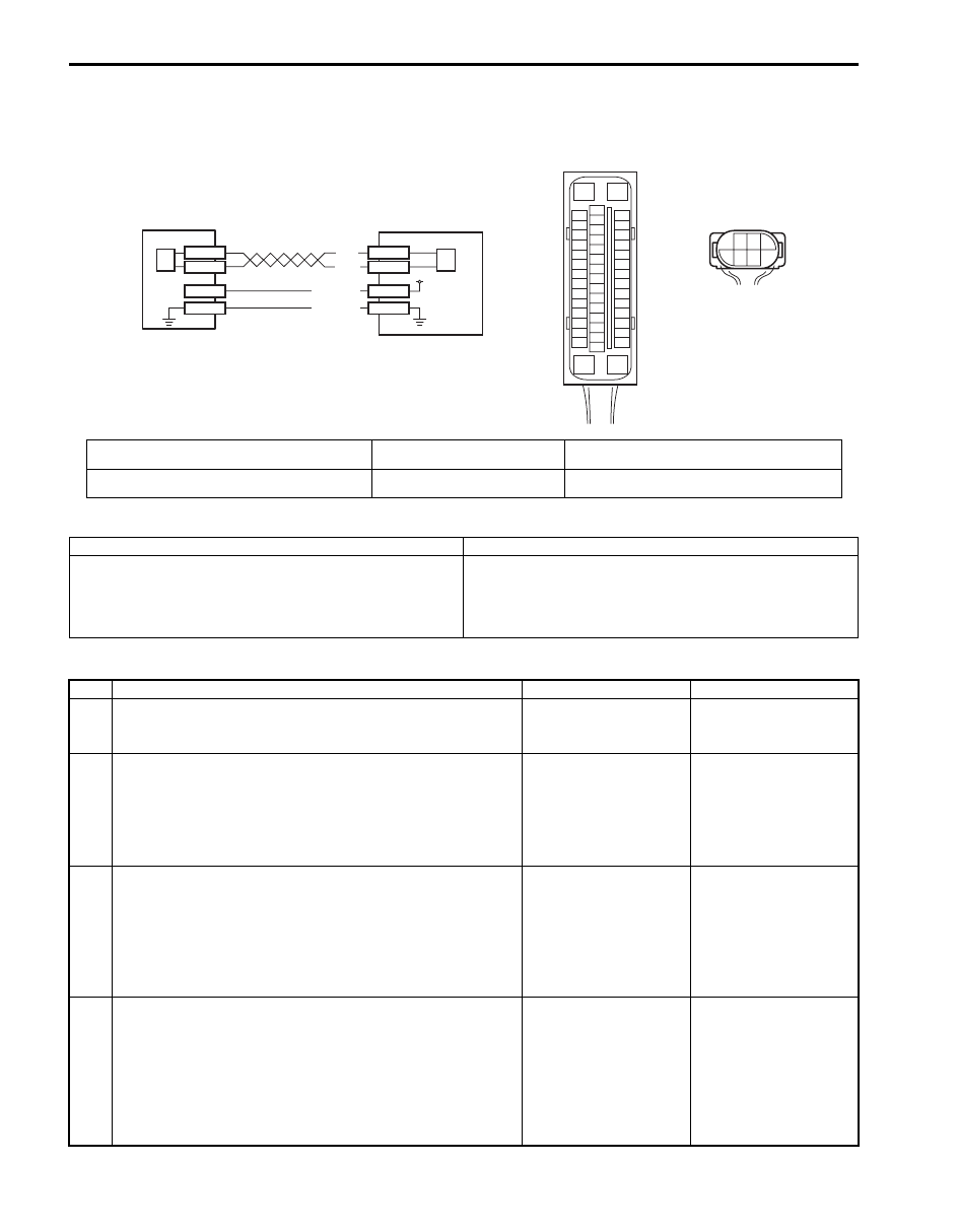
DTC C1073: Lost Communication With Yaw Rate / G Sensor Assembly

S6JB0A4604032

Wiring Diagram

DTC Detecting Condition and Trouble Area

DTC Troubleshooting

[A]

E53

16

1

15

2

3

4

5

6

7

8

9

10

11

12

13

14

17

18

19

20

21

22

23

24

25

26

27

28

29

30

31

32

33

34

35

36

37

38

39

40

41

42

43

44

45

46

47

E53-29
E53-25

E53-37

E53-31

L39-3

L39-5

BLK

WHT

L39-2
L39-1

12V

PNK/GRN

PNK/WHT

[B]

L39

3

5

2 1

4

6

1

2

3

2

I6JB01460022-03

[A]: ESP

® control module connector (viewed from 

terminal side)

1. Yaw rate / G sensor assembly

3. ESP

® hydraulic unit control module assembly

[B]: Yaw rate / G sensor assembly connector (viewed 

from harness side)

2. CAN driver (for yaw rate / G 

sensor assembly)

DTC Detecting Condition

Trouble Area

CAN line communication error in ESP

® control module 

and yaw rate / G sensor assembly is detected.

• CAN communication circuit (for yaw rate / G sensor 

assembly)

• Yaw rate / G sensor assembly
• ESP

® control module

Step

Action

Yes

No

1

Was “Electronic Stability Program Check” performed?

Go to Step 2.

Go to “Electronic 
Stability Program 
Check”.

2

DTC check for ESP

®

1) Connect scan tool to DLC with ignition switch turned 

OFF.

2) Turn ignition switch ON and check DTC for ESP

®.

Is DTC C1057 detected?

Go to applicable DTC 
diag. flow.

Go to Step 3.

3

Check each control module connectors
1) Check connection of connectors of all control modules 

communicating by means of CAN (for yaw rate / G 
sensor assembly).

2) Check DTC for ESP

®.

Is DTC C1073 detected?

Go to Step 4.

Check for intermittent 
trouble referring to 
“Intermittent and Poor 
Connection Inspection 
in Section 00”.

4

CAN communication circuit check
1) Turn ignition switch to OFF position.
2) Disconnect connectors of ESP

® control module and yaw 

rate / G sensor assembly.

Is each CAN communication circuit between ESP

®

 control 

module and yaw rate / G sensor assembly opened, shorted 
or high resistance?

Repair or replace the 
CAN communication 
line.

Go to Step 5.

Electronic Stability Program:  4F-37

DTC C1075 / 1076 / 1077 / 1078: Steering Angle Sensor / Master Cylinder Pressure Sensor / 
Longitudinal G Sensor / Lateral G Sensor in Yaw Rate / G Sensor Assembly Calibration Incomplete

S6JB0A4604033

DTC Detecting Condition and Trouble Area

DTC Troubleshooting

5

Check yaw rate / G sensor assembly
1) Substitute a known-good yaw rate / G sensor assembly.
2) Connect connectors to ESP

® control module and yaw 

rate / G sensor assembly.

3) Clear all DTC(s) and check DTC for ESP

®.

Is DTC C1073 still detected?

Substitute a known-
good ESP

® hydraulic 

unit / control module 
assembly and recheck.

Yaw rate / G sensor 
assembly was 
malfunction.

Step

Action

Yes

No

DTC Detecting Condition

Trouble Area

C1075:
Missing steering angle sensor calibration point data is 
detected.

• Steering angle sensor
• Steering angle sensor calibration is incompleted
• ESP

® control module

C1076:
Master cylinder pressure sensor calibration is 
incompleted.

• Master cylinder pressure sensor
• Master cylinder pressure sensor calibration is 

incompleted

• ESP

® control module

C1077:
Longitudinal G sensor in yaw rate / G sensor assembly 
calibration is incompleted. (for 4WD vehicle)

• Yaw rate / G sensor assembly
• Longitudinal G sensor calibration is incompleted
• ESP

® control module

C1078:
Lateral G sensor in yaw rate / G sensor assembly 
calibration is incompleted.

• Yaw rate / G sensor assembly
• Lateral G sensor calibration is incompleted
• ESP

® control module

Step

Action

Yes

No

1

Was “Electronic Stability Program Check” performed?

Go to Step 2.

Go to “Electronic 
Stability Program 
Check”
.

2

DTC check for ESP

®

1) Connect scan tool to DLC with ignition switch turned 

OFF.

2) Turn ignition switch ON and check DTC for ESP

®.

Is there any DTC(s) other than C1075, C1076, C1077 and 
C1078?

Go to applicable DTC 
diag. flow.

Go to Step 3.

3

Check sensor calibration
1) Calibrate all sensors referring to “Sensor Calibration”.
2) Clear all DTC(s) and check DTC for ESP

®.

Is DTC C1075, C1076, C1077 and/or C1078 still detected?

DTC C1075: Replace 
steering angle sensor.
DTC C1076: Replace 
ESP

® hydraulic unit / 

control module 
assembly.
DTC C1077 / 1078: 
Replace yaw rate / G 
sensor assembly.

Calibration was 
incompleted.

4F-38 Electronic Stability Program: 

DTC C1090: ECM Detect Rolling Counter Failure from ESP

® Control Module

S6JB0A4604034

DTC Detecting Condition and Trouble Area

DTC Troubleshooting

DTC C1091 / 1092 / 1093: ECM / TCM / 4WD Control Module Data in CAN Line Failure

S6JB0A4604035

DTC Detecting Condition and Trouble Area

DTC Troubleshooting

DTC U1073: Control Module Communication Bus Off

S6JB0A4604036

Refer to “DTC U1073: Control Module Communication Bus Off (Petrol Engine Model) in Section 4E”.

DTC U1100: Lost Communication with ECM (Reception Error)

S6JB0A4604037

Refer to “DTC U1100: Lost Communication with ECM (Reception Error) (Petrol Engine Model) in Section 4E”.

DTC Detecting Condition

Trouble Area

ESP

® control module rolling counter failure is detected by 

ECM.

• CAN communication circuit
• ECM
• ESP

® control module

Step

Action

Yes

No

1

Was “Electronic Stability Program Check” performed?

Go to Step 2.

Go to “Electronic 
Stability Program 
Check”.

2

DTC check for ESP

®

1) Connect scan tool to DLC with ignition switch turned 

OFF.

2) Turn ignition switch ON and check DTC for ESP

®.

Is there any DTC(s) other than C1038 and C1090?

Go to applicable DTC 
diag. flow.

Go to Step 3.

3

DTC check for ECM
1) Check DTC for ECM.

Is DTC U0073 and/or DTC U0121 detected?

Go to applicable DTC 
diag. flow.

Substitute a known-
good ESP

® hydraulic 

unit / control module 
assembly and recheck.

DTC Detecting Condition

Trouble Area

C1091:
ECM sent invalid signal to ESP

® control module.

• Engine control system
• ECM
• ESP

® control module

C1092:
TCM sent invalid signal to ESP

® control module. (for A/T 

model)

• A/T system
• TCM
• ESP

® control module

C1093:
4WD control module sent invalid signal to ESP

® control 

module. (if equipped 4WD control module)

• 4WD control system
• 4WD control module
• ESP

® control module

Step

Action

Yes

No

1

Was “Electronic Stability Program Check” performed?

Go to Step 2.

Go to “Electronic 
Stability Program 
Check”.

2

DTC check other control module than ESP

®

1) Check DTC for ECM, TCM and/or 4WD control module.

Is there any DTC(s)?

Go to applicable DTC 
diag. flow.

Substitute a known-
good ESP

® hydraulic 

unit / control module 
assembly and recheck.

Electronic Stability Program:  4F-39

DTC U1101: Lost Communication with TCM (Reception Error)

S6JB0A4604038

Wiring Diagram

WHT

RED

WHT

RED

WHT/BLU

WHT

RED

WHT

RED

E91-22 

E91-23

E53-13

E53-44

E53-46

WHT/BLU

WHT/RED

E23-19

E23-4

G31-1

G31-3

G44-19

G44-18

WHT

RED

WHT

RED

E92-17

E92-7

[F]

G44

1

2

3

4

5

6

7

8

9

10

11

14

15

16
36

34 33 32 31 30 29

24 23

37

18

19

20

[C]

6

5

16 15 14 13 12 11

4 3

24 23

21

22

10 9

8

7

2

1

19

20

18 17

E92

[G]

1

2

3

4

5

6

7

8

9

10

11

17

1615141312

2221201918

G28

[D]

G31

1

2

3

4

7

8

9

10

11

14

15

16
36

34

35

24 23

21

22

28 27

25

26

37

39 38

40

18 17

13 12

19

20

E91

1

2

3

10

11

12

16

17

18

15 14 13

19

20

21

25

26

5

6

[E]

G28-8

G28-10

G45-9

G45-10

WHT/RED

E53-42

WHT

RED

WHT

RED

[A]

E53

16

1

15

2

3

4

5

6

7

8

9

10

11

12

13

14

17

18

19

20

21

22

23

24

25

26

27

28

29

30

31

32

33

34

35

36

37

38

39

40

41

42

43

44

45

46

47

[H]

G45

10 9

3 2 1

1

3

4

9

5

7

6

8

G31-2

G31-4

10

[B]

2 1

E23

3

4

18

19

5

6

7

10

11

17

20

47 46

49

50

51

21

22

52

16

25

9

24

14

29

55

57

5453

59

60

58

26

27

28

15
30

56

48

32 31

34

35

36

37

40

42

3938

44

45

43

41

33

12

13

23

8

G24-6

G24-5

WHT

RED

E66-26

E66-32

WHT/BLU

WHT/RED

[I ]

1

3

7

15

16

17

18

19

20

21

22

23

24

25

26

27

28

29

30

31

32

2

4

6

8

9

10

11

12

13

14

5

E66

[K]

[J]

2

2

11

I6JB0A460006-01

[A]: ESP

® control module connector (viewed from terminal side)

1. ESP

® hydraulic unit / control module assembly

[B]: ECM connector (viewed from harness side) (petrol engine model)

2. ECM

[C]: TCM connector (viewed from harness side)

3. TCM

[D]: BCM connector (viewed from harness side)

4. BCM

[E]: 4WD control module connector (viewed from harness side)

5. 4WD control module (if equipped)

[F]: Keyless start control module connector (viewed from harness side)

6. Keyless start control module (if equipped)

[G]: Combination meter connector (viewed from harness side)

7. Combination meter

[H]: Steering angle sensor connector (viewed from harness side)

8. Steering angle sensor

[I]: ECM connector (viewed from harness side) (diesel engine model)

9. Junction connector

[J]: Petrol engine model

10. Data link connector (DLC)

[K]: Diesel engine model

11. Immobilizer control module (if equipped)


Content   ..  295  296  297  298   ..