Suzuki Grand Vitara JB416 / JB420 / JB419. Service manual - part 276
 

  Index      Suzuki     Suzuki Grand Vitara JB416 / JB420 / JB419 - service and repair manual 2007 year


Search            copyright infringement  


Content   ..  274  275  276  277   ..


Suzuki Grand Vitara JB416 / JB420 / JB419. Service manual - part 276


4C-7 Rear Brakes: 

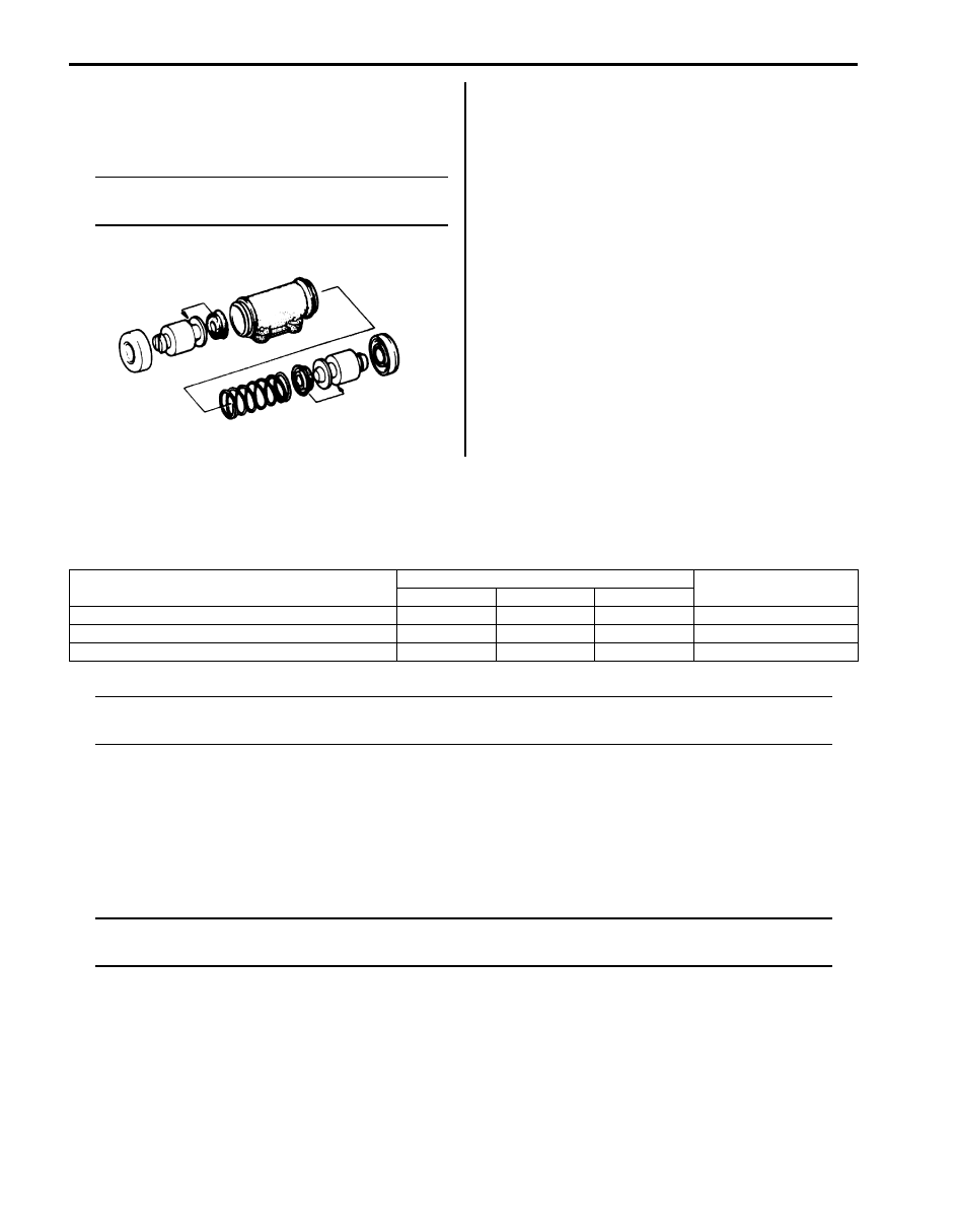
Wheel Cylinder Inspection

S6JB0A4306008

Inspect wheel cylinder disassembled parts for wear, 
cracks, corrosion or damage.

NOTE
Clean wheel cylinder components with brake 
fluid.


Rear Brake Back Plate Removal and Installation

S6JB0A4306009

Removal
Refer to “Rear Wheel Hub Assembly Removal and 
Installation in Section 2C”.

Specifications

Tightening Torque Specifications

S6JB0A4307001

NOTE
The specified tightening torque is also described in the following.
“Rear Drum Brake Assembly Components”


Reference:
For the tightening torque of fastener not specified in this section, refer to “Fastener Information in Section 0A”.

Special Tools and Equipment

Recommended Service Material

S6JB0A4308001

NOTE
Required service material is also described in the following.
“Rear Drum Brake Assembly Components”


IYSQ01430019-01

Fastening part

Tightening torque

Note

N

m

kgf-m

lb-ft

Wheel nut

100

10.0 

72.5

)

Wheel cylinder mounting bolt

13

1.3 

9.5

)

Brake pipe flare nut

16

1.6 

12.0

)

Parking Brake:  4D-1

Brakes

Parking Brake

Component Location

Parking Brake Cable Location

S6JB0A4403001

I5JB0A440001-04

4D-2 Parking Brake: 

Repair Instructions

Parking Brake Check and Adjustment

S6JB0A4406001

Check
Hold center of parking brake lever grip and pull it up with 
200 N (20 kg, 44 lbs) force.
With parking brake lever pulled up as shown, count 
ratchet notches.
There should be 5 to 7 notches.
Also, check if both right and left rear wheels are locked 
firmly.
To count number of notches easily, listen to click sounds 
that ratchet makes while pulling parking brake lever 
without pressing its button.
One click sound corresponds to one notch.
If number of notches is out of specification, adjust cable 
by referring to adjustment procedure to obtain specified 
parking brake stroke.

NOTE
Check tooth tip of each notch for damage or 
wear. If any damage or wear is found, replace 
parking brake lever.


Adjustment

NOTE
Make sure for the following conditions before 
cable adjustment.
• No air is trapped in brake system.
• Brake pedal travel is proper.
• Brake pedal has been depressed a few 

times with about 300 N (30 kg, 66 lbs) load.

• Parking brake lever has been pulled up a 

few times with about 200 N (20 kg, 44 lbs) 
force.
If parking brake cable is replaced with new 
one, pull up parking brake lever a few 
times with about 500 N (50 kg, 110 lbs) 
force.

• Rear brake shoes are not worn beyond 

limit, and self adjusting mechanism 
operates properly.


After confirming that above 5 conditions are all satisfied, 
adjust parking brake lever stroke by loosening or 
tightening adjusting nut (1).

NOTE
Check brake drum for dragging after 
adjustment.


Parking brake stroke
When lever is pulled up at 200 N (20 kg, 44 lbs): 5 to 
7 notches

T: Top side

3. Equalizer

8. Parking brake shoe lever

[a]: For 5door model

F: Front side

4. Parking cable bracket

9. Parking cable clamp nut

[b]: For 3door model

R: Right side

5. Parking cable bracket bolt

10. Parking cable clamp bolt

: 11 N

⋅m (1.1 kgf-m, 8.0 lb-ft)

1. Parking brake lever assembly

6. Parking cable cap nut

11. Parking cable hanger bolt

: 25 N

⋅m (2.5 kgf-m, 18.0 b-ft)

2. Parking brake lever bolt

7. Brake back plate

12. Adjusting nut

: 10 N

⋅m (1.0 kgf-m, 7.5 lb-ft)

I3JA01440003-01

2. Brake cable

1

2

I5JB0A430002-02

Parking Brake:  4D-3

Parking Brake Lever Removal and Installation

S6JB0A4406002

CAUTION

!


For ESP model, the yaw rate / G sensor is set 
alongside the parking brake lever. When 
removing and installing the parking brake 
lever, do not use an impact wrench.
Otherwise, the yaw late / G sensor may be 
damaged by shock of impact wrench.


Removal

1) Block vehicle wheels and release parking brake 

lever.

2) Remove console box. 
3) Disconnect lead wire of parking brake switch at 

coupler.

4) Remove parking brake cable adjusting nut (1).

5) Remove parking brake lever bolts (4) and then 

remove parking brake lever assembly (1) from 
equalizer (3).

6) Remove equalizer (3) from parking brake cable (2).

NOTE
Don’t disassemble parking brake lever 
switch. It must be removed and installed as a 
complete switch assembly.


Installation
Install in reverse order of removal procedure, noting the 
following points.
• Check equalizer inclined angle.

Equalizer inclined angle
“a”: within 15 degrees

Tightening torque
Parking brake lever bolt (a):  25 N·m (2.5 kgf-m, 
18.0 lb-ft)

1) After all parts are installed, parking brake lever 

needs to be adjusted. Refer to “Parking Brake Check 
and Adjustment”.

2) Check brake drum for dragging and brake system for 

proper performance. After removing vehicle from 
hoist, brake test should be performed.

2. Brake cable

5. Pin

1

2

I5JB0A430002-02

I5JB0A440004-01

1. Parking brake cable

4. Parking brake lever bolt

2. Equalizer

5. Parking brake lever

3. Pin

I5JB0A440005-01


Content   ..  274  275  276  277   ..