Suzuki Grand Vitara JB416 / JB420 / JB419. Service manual - part 212
 

  Index      Suzuki     Suzuki Grand Vitara JB416 / JB420 / JB419 - service and repair manual 2007 year


Search            copyright infringement  


Content   ..  210  211  212  213   ..


Suzuki Grand Vitara JB416 / JB420 / JB419. Service manual - part 212


1K-8 Exhaust System: For Diesel Engine Model

Repair Instructions

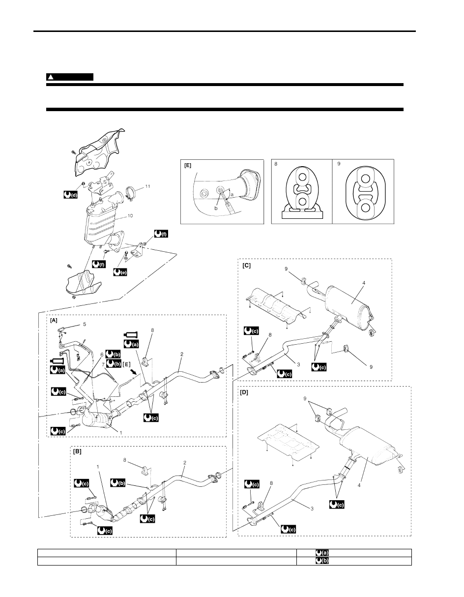
Exhaust System Components

S6JB0A1B26001

WARNING

!


To avoid the danger of being burned, do not touch the exhaust system when the system is hot. Any 
service on the exhaust system should be performed when the system is cool.


I6JB0A1B2001-04

[A]: Diesel particulate filter model

3. Exhaust pipe No.3

: 21 N

⋅m (2.1 kgf-m, 15.5 lb-ft)

[B]: Non-Diesel particulate filter model

4. Muffler

: 30 N

⋅m (3.0 kgf-m, 22.0 lb-ft)

Exhaust System: For Diesel Engine Model 1K-9

Exhaust Manifold Removal and Installation

S6JB0A1B26002

For removal and installation, refer to “Intake Manifold 
and Exhaust Manifold Removal and Installation: For F9Q 
Engine in Section 1D”
.

Diesel Particulate Filter Removal and 
Installation

S6JB0A1B26003

WARNING

!


To avoid the danger of being burned, do not 
touch the exhaust system when the system is 
hot. Any service on the exhaust system 
should be performed when the system is 
cool.


CAUTION

!


When replacing diesel particulate filter, 
perform “Initialize diesel PF data” mode of 
SUZUKI scan tool referring to “SUZUKI Tech 
2 Operator's Manual”.


Removal

1) Disconnect negative (–) cable at battery.
2) Remove exhaust gas temperature sensor 2 and 3 

from diesel particulate filter.

3) Remove diesel particulate filter differential pressure 

sensor union nut.

4) Remove diesel particulate filter differential pressure 

sensor pipe from diesel particulate filter.

5) Remove diesel particulate filter.

Installation
Reverse removal procedure noting the following.
• Tighten bolts and nuts to specified torque referring to 

“Exhaust System Components: For Diesel Engine 
Model”.

• When replacing diesel particulate filter, perform 

“Initialize diesel PF data” mode of SUZUKI scan tool 
referring to “SUZUKI Tech 2 Operator's Manual”.

Specifications

Tightening Torque Specifications

S6JB0A1B27001

NOTE
The specified tightening torque is also described in the following.
“Exhaust System Components: For Diesel Engine Model”


Reference:
For the tightening torque of fastener not specified in this section, refer to “Fastener Information in Section 0A”.

Special Tools and Equipment

Recommended Service Material

S6JB0A1B28001

NOTE
Required service material is also described in the following.
“Exhaust System Components: For Diesel Engine Model”


[C]: 3 door model

5. Diesel particulate filter differential 

pressure sensor

: 50 N

⋅m (5.0 kgf-m, 36.5 lb-ft)

[D]: 5 door model

6. Exhaust gas temperature sensor 2

: 35 N

⋅m (3.5 kgf-m, 25.5 lb-ft)

[E]: View [E]

7. Exhaust gas temperature sensor 3

: 25 N

⋅m (2.5 kgf-m, 18.0 lb-ft)

a. 90

°

8. Mounting No.1

: 44 N

⋅m (4.4 kgf-m, 32.0 lb-ft)

b. Flat face

9. Mounting No.2

: Do not reuse.

1. Exhaust pipe No.1

10. Catalytic converter

: : Apply grease 99000-25280 to 

all around thread part.

2. Exhaust pipe No.2

11. Clamp

1K-10 Exhaust System: For Diesel Engine Model

Table of Contents 2- i

2

Section 2

CONTENTS

Suspension

Precautions .................................................2-1

Precautions............................................................. 2-1

Precautions on Suspension .................................. 2-1

Suspension General Diagnosis.............. 2A-1

Diagnostic Information and Procedures............2A-1

Suspension, Wheels and Tires Symptom 

Diagnosis .......................................................... 2A-1

Specifications.......................................................2A-3

Wheel Alignment Specifications.......................... 2A-3

Front Suspension .................................... 2B-1

General Description .............................................2B-1

Front Suspension Construction........................... 2B-1
Front Wheel Alignment Construction .................. 2B-2

Repair Instructions ..............................................2B-2

Front Wheel Alignment Inspection and 

Adjustment ........................................................ 2B-2

Front Strut Assembly Components ..................... 2B-4
Front Strut Assembly Removal and 

Installation......................................................... 2B-5

Front Strut Assembly Disassembly and 

Assembly .......................................................... 2B-6

Front Strut Assembly Check ............................... 2B-7
Front Wheel Hub Assembly and Steering 

Knuckle Components........................................ 2B-8

Front Wheel Hub Assembly Removal and 

Installation......................................................... 2B-8

Steering Knuckle Removal and Installation....... 2B-10
Front Wheel Hub, Disc, Nut and Bearing 

Check.............................................................. 2B-11

Suspension Control Arm Removal and 

Installation.......................................................2B-11

Suspension Control Arm / Bushing 

Disassembly and Assembly ............................2B-12

Suspension Control Arm / Steering Knuckle 

Check.............................................................. 2B-13

Suspension Control Arm Bushing Check.......... 2B-13
Suspension Control Arm Joint Check ...............2B-13
Front Suspension Frame, Stabilizer Bar and/

or Bushings Components................................2B-14

Front Suspension Frame, Stabilizer Bar and/

or Bushings Removal and Installation.............2B-15

Front Suspension Frame Check ....................... 2B-19

Front Stabilizer Bar, Bushing and/or Joint 

Check ..............................................................2B-19

Front Suspension Fasteners Check..................2B-19

Specifications.....................................................2B-20

Tightening Torque Specifications......................2B-20

Special Tools and Equipment ...........................2B-21

Recommended Service Material .......................2B-21
Special Tool ......................................................2B-21

Rear Suspension ..................................... 2C-1

General Description .............................................2C-1

Rear Suspension Construction ...........................2C-1
Rear Wheel Alignment Construction ...................2C-1

Repair Instructions ..............................................2C-2

Rear Wheel Alignment Inspection and 

Adjustment ........................................................2C-2

Rear Shock Absorber and Rear Coil Spring 

Components......................................................2C-4

Rear Shock Absorber Removal and 

Installation .........................................................2C-5

Shock Absorber Check .......................................2C-6
Rear Coil Spring and Bump Stopper Removal 

and Installation ..................................................2C-6

Rear Coil Spring Check.......................................2C-8
Rod and Arm Components..................................2C-9
Control Rod Removal and Installation...............2C-10
Control Rod / Bushing Disassembly and 

Assembly.........................................................2C-11

Control Rod Check............................................2C-12
Trailing Rod Removal and Installation ..............2C-12
Trailing Rod / Bushing Disassembly and 

Assembly.........................................................2C-13

Trailing Rod Check............................................2C-14
Lower Arm Removal and Installation ................2C-14
Lower Arm / Bushing Disassembly and 

Assembly.........................................................2C-15

Lower Arm Check..............................................2C-16
Upper Arm Removal and Installation ................2C-16
Upper Arm / Bushing Disassembly and 

Assembly.........................................................2C-18

Upper Arm Check..............................................2C-18
Rear Suspension Frame Components..............2C-19
Rear Suspension Frame Removal and 

Installation .......................................................2C-19


Content   ..  210  211  212  213   ..