Suzuki Grand Vitara JB416 / JB420 / JB419. Service manual - part 209
 

  Index      Suzuki     Suzuki Grand Vitara JB416 / JB420 / JB419 - service and repair manual 2007 year


Search            copyright infringement  


Content   ..  207  208  209  210   ..


Suzuki Grand Vitara JB416 / JB420 / JB419. Service manual - part 209


1J-26 Charging System: For Diesel Engine Model

c) Remove pin from brush holder.

6) Install insulator (3).
7) Install rear end cover (2) to coil assembly and tighten 

rear end cover nut (1) to specified torque.

8) Make sure that rotor turns smoothly.

Drive End Frame / Bearing Disassembly and 
Assembly

S6JB0A1A26010

Disassembly

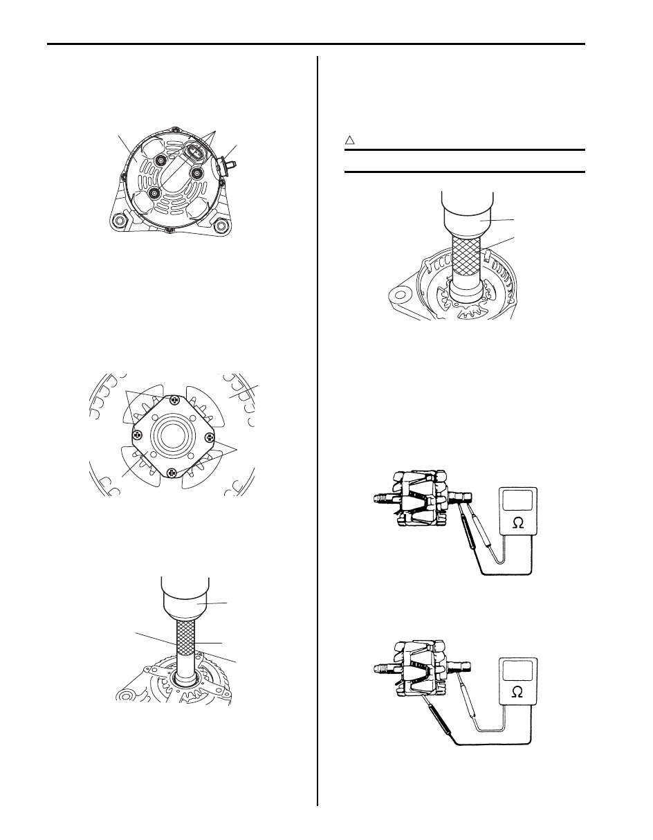
1) Loosen screw (3) and then remove bearing retainer 

(1) from drive end frame (2).

2) Push out drive end bearing by using hydraulic press 

(1) and special tools.

Special tool
(A):  09913–75821 

Assembly

1) Press-fit drive end bearing by using special tools and 

press (1).

Special tool
(A):  09913–76010 

CAUTION

!


Be sure to use new bearing.


2) Install bearing retainer to drive end frame and tighten 

screw.

Generator Inspection

S6JB0A1A26005

Rotor

1) Using an ohmmeter, check for continuity between 

slip rings of rotor. If there is no continuity, replace the 
rotor assembly.

2) Using an ohmmeter, check that there is no continuity 

between slip ring and rotor. If there is continuity, 
replace the rotor assembly.

3) Check slip rings for roughness or scoring. If rough or 

scored, replace the rotor assembly.

2

1

3

I5JB0B1A0011-01

3

1

3

2

I5JB0B1A0019-01

1

A

I5JB0B1A0020-01

1

A

I5JB0B1A0021-01

IYSQ011A0042-01

IYSQ011A0043-01

Charging System: For Diesel Engine Model 1J-27

Stator

1) Check resistance between the following leads of 

stator. If there is no continuity, replace coil assembly.

Stator lead resistance

2) Using an ohmmeter, check that there is no continuity 

between coil leads and stator core. If there is 
continuity, replace coil assembly.

Brush and Brush Holder
Check each brush for wear by measuring its length (a) 
as shown. If the brush is found worn down, replace the 
brush. 

Rectifier

1) Check continuity of rectifier by using an ohm meter.
2) Reverse the polarity of the tester probes and repeat 

Step 1).

3) Check that one shows continuity and the other 

shows no continuity.
If there is continuity, replace coil assembly.

Bearing
• Check that drive and bearing is not rough or worn.

• Check that end housing bearing is not rough or worn.

Stator lead 

Resistance

1 - 2

continuity

1 - 3
4 - 5
4 - 6

1

2

3

4

5

6

I5JB0B1A0022-01

I5JB0B1A0023-01

a

I5JB0B1A0024-02

I5JB0B1A0026-01

IYSQ011A0051-01

1J-28 Charging System: For Diesel Engine Model

Accessory Drive Belt and Idler Pulley Removal 
and Installation

S6JB0A1A26006

Removal

WARNING

!


Disconnect negative (–) cable at battery 
before removing and installing generator 
belt.


1) Remove engine under cover.
2) Loosen tensioner by turning the tensioner (1) 

clockwise.

3) While holding the tensioner and belt loose.
4) Loosen tensioner bolt No.1 (2) and remove breather 

front No.1 hose clip (3).

5) Remove accessory drive belt (4).

CAUTION

!


Do not apply any oil or grease to the 
accessory drive belt.


6) Loosen idler pulley bolt (7) and then remove idler 

pulley (5) and adapter (6).

Installation

1) Install adapter (6) and then tighten adapter.
2) Install idler pulley (5) and then tighten idler pulley 

bolt (7) to specified torque.

Tightening torque
Idler pulley bolt (b):  50 N·m (5.0 kgf-m, 36.5 lb-ft)

3) Install accessory drive belt (4).
4) Tighten tensioner bolt No.1 (2) and install breather 

front No.1 hose clip (3).

Tightening torque
Accessory drive belt and belt tensioner bolt 
No.1 (a):  50 N·m (5.0 kgf-m, 36.5 lb-ft)

5) Loosen tensioner by turning the tensioner (1) 

clockwise.

6) While holding the tensioner, install accessory drive 

belt (4).

NOTE
Make sure that the belt fits each pulley’s 
groove properly.


7) Install engine under cover.

1

2

3

4

5

6

5

7

I5JB0B1A0027-01

1

2,(a)

3

4

5

6

5

7,(b)

I5JB0B1A0028-02

Charging System: For Diesel Engine Model 1J-29

Accessory Drive Belt Inspection

S6JB0A1A26007

Check accessory drive belt for cracks, cuts, deformation, 
wear and cleanliness, and replace as required.

Accessory Drive Belt Tensioner Removal and 
Installation

S6JB0A1A26008

Removal

1) Remove accessory drive belt referring to “Accessory 

Drive Belt and Idler Pulley Removal and Installation: 
For Diesel Engine Model”.

2) Remove accessory drive belt tensioner.

Installation

1) Install accessory drive belt tensioner.
2) Tighten accessory drive belt tensioner bolt No.1 and 

No.2 to specified torque.

Tightening torque
Accessory drive belt tensioner bolt No.2 (a):  22 
N·m (2.2 kgf-m, 16.0 lb-ft)
Accessory drive belt tensioner bolt No.1 (b):  50 
N·m (5.5 kgf-m, 36.5 lb-ft)

3) Install accessory drive belt referring to “Accessory 

Drive Belt and Idler Pulley Removal and Installation: 
For Diesel Engine Model”.

Specifications

Charging System Specifications

S6JB0A1A27001

Battery

Battery
: 95D26L (63AH/5HR) 12 V

Generator

(a)

(b)

I5JB0B1A0029-01

Battery type

95D26L

Rated capacity

AH/5HR, 12 Volts

63

Electrolyte

L (US / lmp pt.)

4.0 (8.45 / 7.04)

Electrolyte S.G.

1.28 when fully charged at 20 

°C (68 °F)

Type

150 A type

Rated voltage

12 V

Nominal output

150 A

Permissible max. speed

18,000 r/min.

No-load speed

1500 r/min. (rpm)

Regulated voltage

14.2 – 14.8 V

Exposed brush length

Standard: 10.5 mm (0.41 in.)
Limit: 4.5 mm (0.18 in.)

Permissible ambient temperature

–30 – 90 

°C (–22 to 194 °F)

Polarity

Negative ground

Rotation

Clockwise viewed from pulley side


Content   ..  207  208  209  210   ..