Suzuki Grand Vitara JB416 / JB420 / JB419. Service manual - part 200
 

  Index      Suzuki     Suzuki Grand Vitara JB416 / JB420 / JB419 - service and repair manual 2007 year


Search            copyright infringement  


Content   ..  198  199  200  201   ..


Suzuki Grand Vitara JB416 / JB420 / JB419. Service manual - part 200


1I-8 Starting System: For Petrol Engine Model

Brush Spring
Inspect brush springs for wear, damage or other 
abnormal conditions. Replace if necessary.

Brush spring tension
Standard: 1.8 kg (3.97 lb)
Limit: 0.3 kg (0.67 lb)

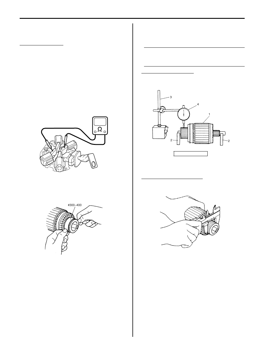
Brush Holder
• Check movement of brush in brush holder. If brush 

movement within brush holder is sluggish, check 
brush holder for distortion and sliding faces for 
contamination. Clean or correct as necessary.

• Check for continuity across insulated brush (positive 

side) and grounded brush (negative side). If continuity 
exists, brush holder is grounded due to defective 
insulation and should be replaced.

Armature
• Inspect commutator for dirt or burn. Correct with 

sandpaper or lathe, if necessary.

• Check commutator for uneven wear with armature (1) 

supported on V-blocks (2). If deflection of dial gauge 
(4) pointer exceeds limit, repair or replace.

NOTE
The following specification presupposes that 
armature is free from bend. Bent armature 
must be replaced.


Commutator out of round
Standard: 0.05 mm (0.002 in.) or less
Limit: 0.4 mm (0.016 in.)

• Inspect commutator for wear. If diameter is below 

limit, replace armature.

Commutator outside diameter
Standard: 29.4 mm (1.16 in.)
Limit: 28.8 mm (1.13 in.)

I4RS0A190004-01

IYSQ01190034-01

3. Magnetic stand

IYSQ01190035-01

IYSQ01190036-01

Starting System: For Petrol Engine Model 1I-9

• Inspect commutator for insulator depth. Correct or 

replace if below limit.

Commutator insulator depth “a”
Standard: 0.4 – 0.6 mm (0.016 – 0.024 in.)
Limit: 0.2 mm (0.008 in.)

Ground test
Check the commutator and armature core. If there is 
continuity, armature is grounded and must be replaced.

Open circuit test
Check for continuity between segments. If there is no 
continuity at any test point, there is an open circuit and 
the armature must be replaced.

Gears
Inspect internal gear and the planetary gears for wear, 
damage or other abnormal conditions. Replace if 
necessary.

Pinion and Over-Running Clutch
• Inspect pinion for wear, damage or other abnormal 

conditions. Check that clutch locks up when turned in 
direction of drive and rotates smoothly in reverse 
direction. Replace if necessary.

• Inspect spline teeth for wear or damage. Replace if 

necessary. Inspect pinion for smooth movement.

Front Housing Bush
Inspect bush for wear or damage. Replace if necessary.

[A]: Correct

1. Commutator segment

[B]: Incorrect

2. Insulator

I5JB0A190003-01

IYSQ01190038-01

IYSQ01190039-01

IYSQ01190040-01

IYSQ01190041-01

IYSQ01190042-01

IYSQ01190043-01

1I-10 Starting System: For Petrol Engine Model

Specifications

Starting Motor Specifications

S6JB0A1917001

1.2 kW Type [1.4 kW Type]

Tightening Torque Specifications

S6JB0A1917002

NOTE
The specified tightening torque is also described in the following.
“Starting Motor Dismounting and Remounting: For Petrol Engine Model”
“Starting Motor Components: For Petrol Engine Model”


Reference:
For the tightening torque of fastener not specified in this section, refer to “Fastener Information in Section 0A”.

Special Tools and Equipment

Recommended Service Material

S6JB0A1918001

NOTE
Required service material is also described in the following.
“Starting Motor Components: For Petrol Engine Model”


Voltage

12 volts

Output

1.2 kW [1.4 kW]

Rating

30 seconds

Direction of rotation

Clockwise as viewed from pinion side

Brush length

Standard: 12.3 mm (0.48 in.)

Limit: 5.5 mm (0.22 in.)

Number of pinion teeth

8

Performance

Condition

Guarantee

Around 
at 20 

°C (68 °F)

No load characteristic

11.0 V

90 A maximum
2370 r/min minimum [2000 r/min minimum]

Load characteristic

7.5 V

300 A

10.65 N

⋅m (1.065 kgf-m, 7.70 lb-ft) minimum

[11.0 N

⋅m (1.1 kgf-m, 7.95 lb-ft) minimum]

840 r/min minimum

Locked characteristic

4.0 V

[3.0 V]

780 A maximum
[860 A maximum]
20 N

⋅m (2.0 kgf-m, 14.5 lb-ft) minimum

Magnetic switch operating voltage 8 volts maximum

Fastening part

Tightening torque

Note

N

m

kgf-m

lb-ft

Starting motor battery cable nut

11

1.1 

8.0

)

Starting System: For Diesel Engine Model 1I-11

For Diesel Engine Model

General Description

Cranking Circuit Introduction

S6JB0A1921001

The cranking circuit consists of the battery, starting motor, ignition switch, and related electrical wiring. These 
components are connected electrically.

Starting Motor Circuit Description

S6JB0A1921002

• The magnetic switch coils are magnetized when the ignition switch is closed.
• The resulting plunger and pinion drive lever movement causes the pinion to engage the engine flywheel gear and 

the magnetic switch main contacts to close, and cranking takes place.

• When the engine starts, the pinion over-running clutch protects the armature from excessive speed until the switch 

is opened, at which time the return spring causes the pinion to disengage.

I5JB0B190001-01

1. Pinion drive lever

5. Magnetic switch contacts

9. Starting motor

2. Plunger

6. Pinion and over-running clutch

10. Battery

3. Hold-in coil

7. Pull-in coil

11. Ignition and starting motor switch

4. Magnetic switch

8. Return spring

12. Starting motor control relay


Content   ..  198  199  200  201   ..