Suzuki Grand Vitara JB416 / JB420 / JB419. Service manual - part 183
 

  Index      Suzuki     Suzuki Grand Vitara JB416 / JB420 / JB419 - service and repair manual 2007 year


Search            copyright infringement  


Content   ..  181  182  183  184   ..


Suzuki Grand Vitara JB416 / JB420 / JB419. Service manual - part 183


1G-5 Fuel System: For Petrol Engine Model

Repair Instructions

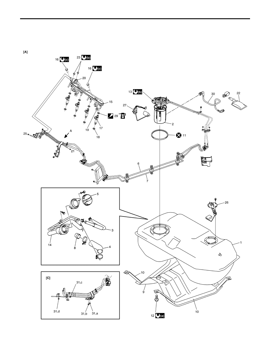
Fuel System Components

S6JB0A1716001

I6JB0A171001-01

Fuel System: For Petrol Engine Model 1G-6

5

2

26

1

11

3

4

8

14

(b)

13

(a)

12

(b)

23

(c)

16

25

27

25

10

9

10

20

15

18

17

19

29

28

21

6

7

[B]

22

30

25

I6JB0A171002-01

[A]: For M16 engine model

11. Fuel pump gasket

24. To fuel tank

[B]: For J20 engine model

12. Fuel tank bolt

25. To EVAP canister purge valve

[C]: View A

13. Fuel pump bolt

26. Sub fuel level sensor

1. Fuel tank

14. Fuel filler neck

27. Main fuel level sensor

2. Fuel pump assembly

15. Fuel delivery pipe

28. To vacuum tank

3. Breather hose

16. Fuel delivery pipe bolt

29. O-ring

: Apply O-ring oil 99000-25320 to O-ring.

4. Fuel tank filler hose

17. Fuel injector

30. Fuel suction hose

5. Fuel filler cap

18. Injector cushion 

31. Fuel pipe bolt

: Tighten bolts as alphabetical order (a through d).

1G-7 Fuel System: For Petrol Engine Model

6. Fuel feed line

19. Fuel delivery pipe insulator

: Do not reuse.

7. Fuel return line

20. Fuel pressure regulator

: 50 N

⋅m (5.0 kgf-m, 36.5 lb-ft)

8. Fuel tank inlet valve

21. To canister

: 11 N

⋅m (1.1 kgf-m, 8.0 lb-ft)

9. Fuel tank protector

22. Fuel suction filter

: 25 N

⋅m (2.5 kgf-m, 18.0 lb-ft)

10. Fuel tank belt

23. Fuel pressure regulator bolt

Fuel System: For Petrol Engine Model 1G-8

Fuel Hose Disconnecting and Reconnecting

S6JB0A1716002

WARNING

!


Before starting the following procedure, be sure to observe “Precautions on Fuel System Service: For 
Petrol Engine Model” in orde
r to reduce the risk or fire and personal injury.


Be sure to connect and clamp each hose correctly as shown in figure.

For Normal Clamp
Fuel tank system

NOTE
Be sure to install hose to spool of pipe surely.


I6JB0A171003-01

1. Pipe

6. Vehicle backward (for M16 engine model)

Vehicle forward (for J20 engine model)

“e”: 33 mm (1.30 in.)

2. Hose

“a”: 3 – 7 mm (0.12 – 0.28 in.)

“f”: 38 mm (1.50 in.)

3. Clamp

“b”: 5 – 12 mm (0.20 – 0.48 in.)

: 2 N

⋅m (0.2 kgf-m, 1.5 lb-ft)

4. Fuel filler hose clamp screw

“c”: 2 mm (0.08 in.)

5. Vehicle forward

“d”: 25 – 30 mm (0.98 – 1.18 in.)


Content   ..  181  182  183  184   ..