Suzuki Grand Vitara JB416 / JB420 / JB419. Service manual - part 165
 

  Index      Suzuki     Suzuki Grand Vitara JB416 / JB420 / JB419 - service and repair manual 2007 year


Search            copyright infringement  


Content   ..  163  164  165  166   ..


Suzuki Grand Vitara JB416 / JB420 / JB419. Service manual - part 165


1D-186 Engine Mechanical: For F9Q Engine

4) Install bearing cap referring to connecting rod and 

bearing cap referring to Step 9) of “Installation” under 
“Piston, Piston Ring and Connecting Rod Removal 
and Installation: For F9Q Engine”
.

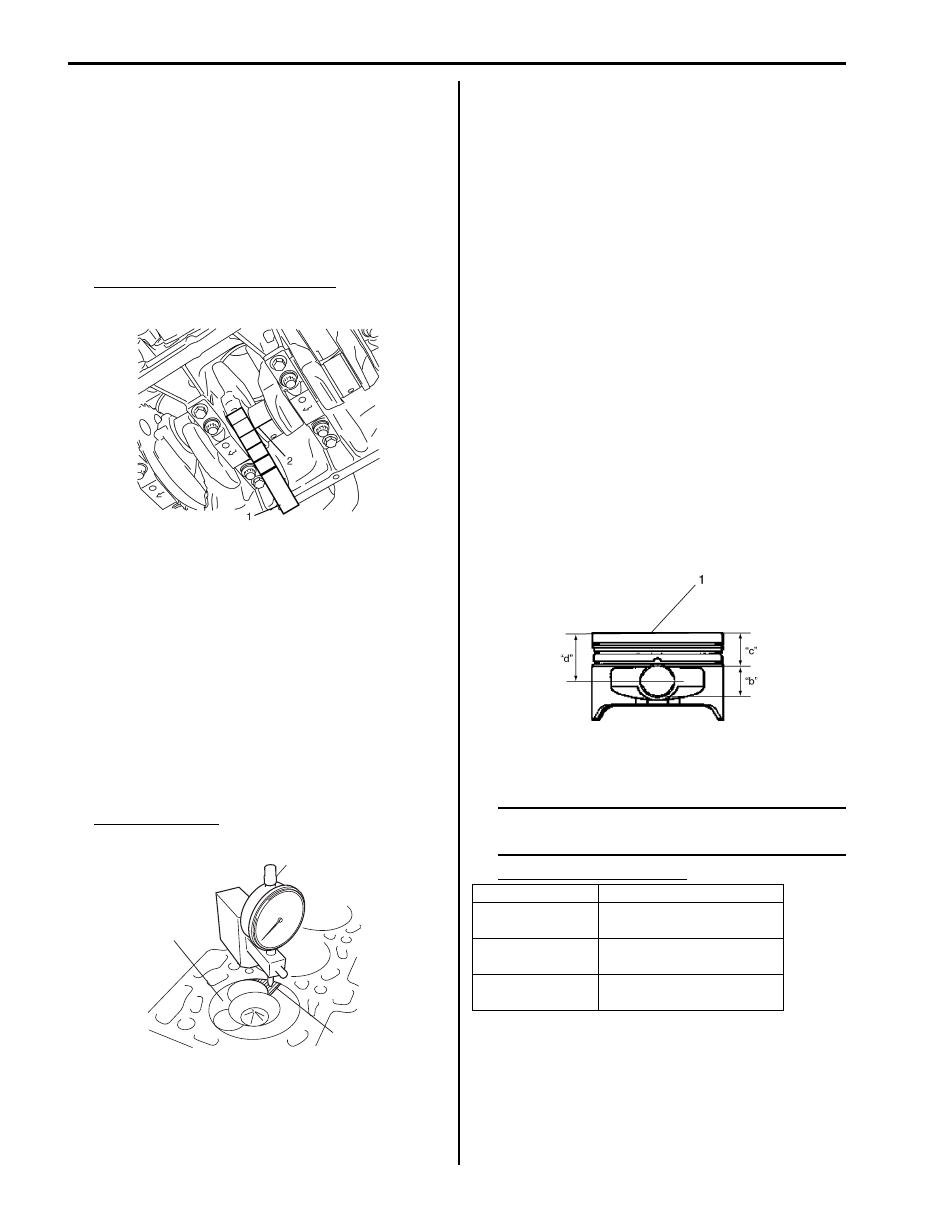
5) Remove cap, and using a scale (1) on gauging 

plastic envelope (2), measure gauging plastic (2) 
width at the widest point (clearance).
If measured clearance is out of specification, use a 
new connecting rod bearing.
After install new bearing, recheck clearance.

Connecting rod bearing clearance
0.027 – 0.086 mm (0.00107 – 0.00338 in.)

6) If clearance can not be brought to its specification 

even by using a new connecting rod bearing and/or 
replace crankshaft.

Piston Protrusion

1) Install piston and connecting rod assembly to 

cylinder block referring to Step 1) through 9) of 
“Install” under “Piston, Piston Ring and Connecting 
Rod Removal and Installation: For F9Q Engine”.

2) Using special tool and dial gauge, measure piston 

protrusion at specified position (2) as shown in figure 
when piston (1) reaches top dead center. Repeat this 
procedure with each piston.If measured protrusion is 
out of specification, proceed to next step.

Piston protrusion
“a”: 0.50 – 0.62 mm (0.0197 – 0.0244 in.)

3) Check connecting rod length referring to 

“Connecting Rod and Related Parts Specification 
(for Reference)” under “Cylinders, Pistons and 
Piston Rings Inspection: For F9Q Engine”.If
 
connecting rod is normal, proceed to next step.

4) Replace piston (1) as follows in order to adjust piston 

protrusion to specified value.
a) Remove piston, and measure the following 

specification.
• Piston pin hole diameter “b”
• Distance “c” between top of piston and top of 

piston pin hole

b) Obtain distance “d” between top of piston and 

center of piston pin hole by formula below.
“d” = “b” / 2 + “c”

c) Using piston protrusion “a” measured at Step 2), 

obtain adjusting distance “e” by formula below.
“e” = “d” + 0.56 mm (0.0220 in.) – “a”
Example:
When distance “d” of removed piston is 47.026 
mm (1.85142 in.), and measured piston 
protrusion “a” is 0.45 mm (0.0177 in.)
Calculated adjusting distance “e” = 47.026 mm 
(1.85142 in.) + 0.56 mm (0.0220 in.) – 0.45 mm 
(0.0177 in.) = 47.136 mm (1.85575 in.)

d) Select new piston so that distance “e” is within 

range of distance “d” of new piston.

NOTE
Piston class (1) is marked on piston top as 
shown in figure.


Available new piston class

I2RH0B140123-01

2

1

I5JB0B140109-01

Piston class (1)

Distance “d”

S

47.026 – 47.066 mm 

(1.85142 – 1.85299 in.)

T

47.068 – 47.108 mm 

(1.85307 – 1.85464 in.)

U

47.110 – 47.150 mm 

(1.85473 – 1.85629 in.)

I5JB0B140110-01

Engine Mechanical: For F9Q Engine 1D-187

e) Replace piston with selected piston.
f) Check piston protrusion, again.

Main Bearing, Crankshaft and Cylinder Block Component

S6JB0A1436068

I5JB0B140132-01

1

5

7

3

2

(a)

6

6

4

3

I5JB0B140111-01

1. Cylinder block

6. Oil jet

2. Flywheel side crankshaft oil seal

7. Bearing cap seal

3. Main bearing

: Do not apply oil between cylinder block and bearing and between, main bearing 
cap and bearing.

: Tighten 20 N

⋅m (2.0 kgf-m, 14.5 lb-ft) and 62° by the specified 

procedure.

4. Thrust bearing

: Do not reuse.

5. Main bearing cap

: Apply engine oil to inside / sliding surface.

1D-188 Engine Mechanical: For F9Q Engine

Main Bearing, Crankshaft and Cylinder Block 
Removal and Installation

S6JB0A1436066

Removal

1) Remove piston and connecting rod referring to 

“Piston, Piston Ring and Connecting Rod Removal 
and Installation: For F9Q Engine”
.

2) Remove heat exchanger referring to “Heat 

Exchanger Removal and Installation: For F9Q 
Engine in Section 1E”,
 if necessary.

3) Loosen main bearing cap bolts in numerical order as 

indicated in figure, and remove them.

4) Remove main bearing cap No.1 using special tool as 

follows.

Special tool
(A):  09917–56510

a) Install special tool to main bearing cap No.1 (1).
b) Pull out main bearing cap No.1 from cylinder 

block by tightening bolt (2) of special tool.

c) Remove main bearing cap from special tool.

5) Remove main bearing caps (No.2 through No.5) and 

crankshaft from cylinder block.

6) Remove main bearings (1) and thrust bearings (2).

7) Disconnect fresh air vent hose (1), and remove oil 

fresh air vent pipe (2) from cylinder block, if 
necessary.

8) Remove oil jet as follows, if necessary.

a) Pack rag into cylinder in order to prevent swart 

from entering.

b) Remove spring stop (1) and spring (2) using 7 

mm (0.28 in.) diameter drill (4).

CAUTION

!


Do not remove ball (3) to prevent swarf from 
entering lubrication circuit.


I5JB0B140112-01

I5JB0B140113-01

1

2

I5JB0B140114-01

1

2

I5JB0B140115-01

I5JB0B140118-01

Engine Mechanical: For F9Q Engine 1D-189

c) Desorb swarf from cylinder and oil jet.
d) Install special tool (A) to drilled hole of oil jet (1).
e) Remove oil jets from cylinder using special tool 

(A) and (B).

Special tool
(A):  09916–48120 
(B):  09916–58120 

Installation

NOTE

• Use new bearing cap bolts. They are 

deformed after tightening once because 
they are plastic deformation tightening 
bolts.

• All parts to be installed must be perfectly 

clean.

• Be sure to oil crankshaft journals, main 

bearings and thrust bearings.

• Main bearings and bearing caps are in 

combination sets. 
Do not disturb such combination and make 
sure that each part goes back to where it 
came from, when installing.


1) Remove oil, old sealant and dust from mating 

surface of cylinder block, bearing caps and 
crankshaft.

2) Using special tool, install oil jets as follows, if 

removed.

Special tool
(A):  09912–86510
(B):  09912–86520

a) Install plate (1) to cylinder block by head 

tightening plate bolts (2).

b) Install guide rod (3) to plate aligning guide rod 

end with oil jet hole.

c) Tighten plate bolts, and remove guide rod.

I5JB0B140116-01

1. Oil jet No.1

4. Oil jet No.4

7. Plate

2. Oil jet No.2

5. Flywheel side

8. Guide rod

3. Oil jet No.3

6. Pushrod

9. Plate bolt

[A]: Oil jet No.2 and No.4

[B]: Oil jet No.1 and No.3

I5JB0B140117-01

I5JB0B140119-01


Content   ..  163  164  165  166   ..