Suzuki Grand Vitara JB416 / JB420 / JB419. Service manual - part 160
 

  Index      Suzuki     Suzuki Grand Vitara JB416 / JB420 / JB419 - service and repair manual 2007 year


Search            copyright infringement  


Content   ..  158  159  160  161   ..


Suzuki Grand Vitara JB416 / JB420 / JB419. Service manual - part 160


1D-166 Engine Mechanical: For F9Q Engine

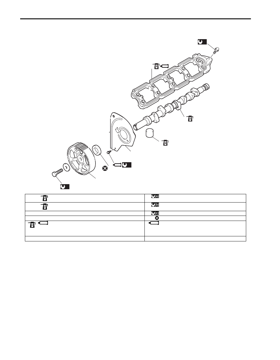
Camshaft and Tappet Components

S6JB0A1436060

6

4

(a)

(b)

3

5

1

2

(c)

I5JB0B140062-02

1. Camshaft

: Apply engine oil to sliding surface.

: 60 N

⋅m (6.0 kgf-m, 43.5 lb-ft)

2. Tappet

: Apply engine oil to sliding surface.

: Tighten 20 N

⋅m (2.0 kgf-m, 14.5 lb-ft) by the specified 

procedure.

3. Camshaft oil seal

: 10 N

⋅m (1.0 kgf-m, 7.5 lb-ft)

4. Camshaft pulley

: Do not reuse.

5. Camshaft housing

: Apply engine oil to sliding surface.
: Apply sealant Loctite FRENETANCH

® to the maing surface of 

camshaft housing and cylinder head.

: Apply sealant Loctite FRENETANCH

® to the bolt thread.

6. Timing belt inner cover

Engine Mechanical: For F9Q Engine 1D-167

Camshaft and Tappet Removal and Installation

S6JB0A1436061

Removal

1) Remove engine assembly referring to “Engine 

Assembly Removal and Installation: For F9Q 
Engine”.

2) Remove timing belt referring to “Timing Belt and Belt 

Tensioner Removal and Installation: For F9Q 
Engine”.

3) Remove injection pump and front bracket referring to 

“Injection Pump Removal and Installation: For Diesel 
Engine Model in Section 1G”.

4) Remove vacuum pump referring to “Vacuum Pump 

Removal and Installation: For F9Q Engine”.

5) Remove CMP sensor referring to “Camshaft Position 

(CMP) Sensor Removal and Installation: For Diesel 
Engine Model in Section 1C”.

6) Remove camshaft pulley as follows.

a) Fix camshaft pulley using special tool.

Special tool
(A):  09917–68221 

b) Loosen camshaft pulley bolt (1), and remove 

camshaft pulley (2).

c) Remove timing belt inner cover (3).

7) Remove cylinder head cover referring to “Cylinder 

Head Cover Removal and Installation: For F9Q 
Engine”.

8) Loosen camshaft housing bolts evenly and gradually 

in numerical order “1” through “10” as shown in 
figure, and remove them.

9) Remove camshaft housing and camshaft from 

cylinder head.

10) Remove camshaft oil seal from camshaft.

11) Remove tappet (1) from cylinder head.

CAUTION

!


Note original position in which each tappet 
was installed when valve lash (clearance) 
adjustment is not necessary.
If each tappet is not installed to original 
position, engine will spoil its original 
performance.


3

2

(A)

1

I5JB0B140063-01

I5JB0B140066-01

1

I5JB0B140065-01

1D-168 Engine Mechanical: For F9Q Engine

Installation

1) Apply engine oil around tappet (1), and then install it 

to cylinder head.

2) Install camshaft to cylinder head as follows.

a) Apply engine oil to sliding surface of each 

camshaft and camshaft journal.

b) Fit camshaft (1) to cylinder head (2).

c) Fit timing belt inner cover (1), and tighten timing 

belt inner cover bolts (2) after applying “A” to bolt 
thread.

“A”:  Thread lock cement  (Loctite 
FRENETANCH®)

Tightening torque
Timing belt inner cover bolt (a):  10 N·m (1.0 
kgf-m, 7.5 lb-ft)

d) Install camshaft pulley (2) to camshaft (4) 

aligning key (1) to groove (3).

e) Tighten camshaft pulley bolt temporarily by 

hand.

f) Turn camshaft pulley clockwise, and stop turning 

crankshaft immediately before mark (1) of 
camshaft pulley (2) with mark (3) of timing belt 
inner cover (4).

g) Install camshaft housing to cylinder head as 

follows.
i)

Remove oil, old sealant and dust from 
sealing surfaces of camshaft housing (1) and 
cylinder head cover.

ii) Apply sealant “A” to sealing surface area of 

camshaft housing (1) using stipple roller (2) 
as shown in figure.

“A”:  Thread lock cement  (Loctite 518®)

1

I5JB0B140065-01

I5JB0B140064-02

I5JB0B140067-01

3

1

4

2

I5JB0B140068-01

I5JB0B140031-01

I5JB0B140069-01

Engine Mechanical: For F9Q Engine 1D-169

iii) Fit camshaft holder to cylinder head.
iv) Apply “A” to camshaft housing bolt thread.
v) Tighten camshaft housing bolts evenly and 

gradually in numerical order (“1” through 
“10”) by repeating tightening sequence two 
or three times until specified torque is 
obtained.

Tightening torque
Camshaft housing bolt (a):  Tighten 20 
N

m (2.0 kgf-m, 14.5 lb-ft) by the specified 

procedure

3) Remove camshaft pulley.
4) Install camshaft oil seal as follows.

a) Fit oil seal (1) to camshaft.
b) Install oil seal to camshaft by tightening bolt (2) 

of special tool until installer (3) of special tool 
comes contact with cylinder head.

Special tool
(A):  09913–56520

c) Remove special tool.

5) Install camshaft pulley (2) to camshaft (4) aligning 

key (1) to groove (3).

6) Tighten camshaft pulley bolt (1) to specified torque 

using special tool.

Special tool
(A):  09917–68221 

Tightening torque
Camshaft pulley bolt (a):  60 N·m (6.0 kgf-m, 43.5 
lb-ft)

7) Install CMP sensor referring to “Camshaft Position 

(CMP) Sensor Removal and Installation: For Diesel 
Engine Model in Section 1C”.

8) Install vacuum pump referring to “Vacuum Pump 

Removal and Installation: For F9Q Engine”.

9) Install injection pump and front bracket referring to 

“Injection Pump Removal and Installation: For Diesel 
Engine Model in Section 1G”.

10) Install timing belt referring to “Timing Belt and Belt 

Tensioner Removal and Installation: For F9Q 
Engine”.

11) Check valve lash (clearance) referring to “Valve Lash 

(Clearance) Inspection: For F9Q Engine”.

12) Install cylinder head cover referring to “Cylinder 

Head Cover Removal and Installation: For F9Q 
Engine”

13) Install engine assembly referring to “Engine 

Assembly Removal and Installation: For F9Q 
Engine”.

I5JB0B140070-01

I5JB0B140071-01

3

1

4

2

I5JB0B140068-01

(A)

1,(a )

I5JB0B140072-02


Content   ..  158  159  160  161   ..