Suzuki Grand Vitara JB416 / JB420 / JB419. Service manual - part 156
 

  Index      Suzuki     Suzuki Grand Vitara JB416 / JB420 / JB419 - service and repair manual 2007 year


Search            copyright infringement  


Content   ..  154  155  156  157   ..


Suzuki Grand Vitara JB416 / JB420 / JB419. Service manual - part 156


1D-150 Engine Mechanical: For F9Q Engine

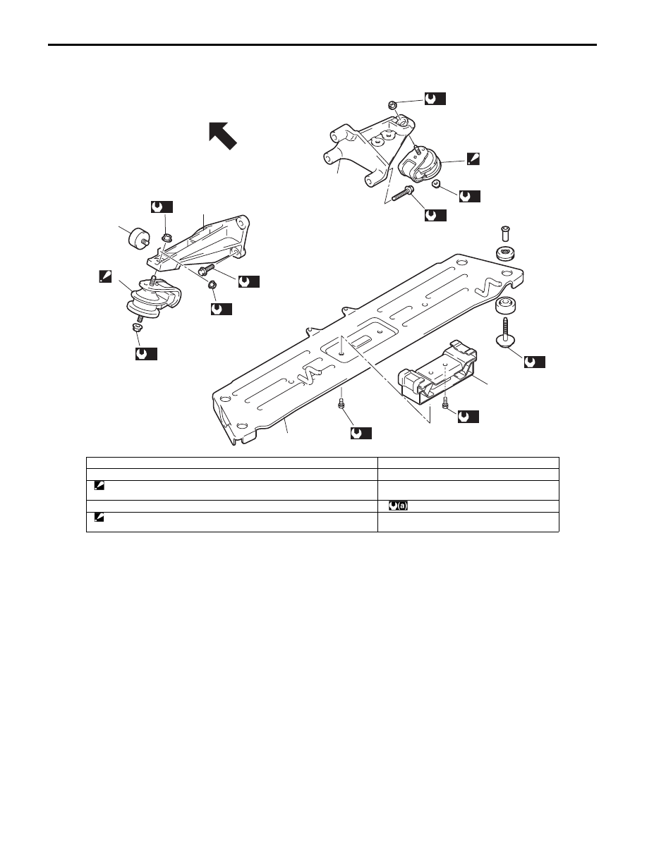
Engine Mounting Components

S6JB0A1436011

3

5

7

6

1

(a)

4

2

(a)

(a)

(a)

(a)

(a)

(a)

(a)

(a)

(a)

A

I5JB0B140039-01

A: Forward

5. Engine left mounting bracket damper

1. Engine right mounting bracket

6. Engine rear mounting

2. Engine right mounting

: Be sure to align dowel pin with dowel hole of engine right mounting bracket.

7. Engine rear mounting bracket

3. Engine left mounting bracket

: 55 N

⋅m (5.5 kgf-m, 40.0 lb-ft)

4. Engine left mounting

: Be sure to align dowel pin with dowel hole of engine left mounting bracket.

Engine Mechanical: For F9Q Engine 1D-151

Engine Assembly Removal and Installation

S6JB0A1436053

WARNING

!


Before servicing fuel system, be sure to 
observe “Precautions on Fuel System 
Service: For Diesel Engine Model in Section 
1G”.


Removal

1) Relief fuel pressure referring to “Fuel Pressure Relief 

Procedure: For Diesel Engine Model in Section 1G”.

2) Remove battery.
3) Drain engine oil referring to “Engine Oil and Filter 

Change (Diesel Engine Model) in Section 0B”.

4) Drain coolant referring to “Cooling System Draining: 

For Diesel Engine Model in Section 1F”.

5) Remove accessory drive belt referring to “Accessory 

Drive Belt and Idler Pulley Removal and Installation: 
For Diesel Engine Model in Section 1J”.

6) Remove shift control lever referring to “Transmission 

Shift Control Lever Removal and Installation: For 
Diesel Engine Model in Section 5B”.

7) Remove exhaust No.1 pipe referring to “Exhaust 

System Components: For Diesel Engine Model in 
Section 1K”
.

8) Remove front and rear propeller shafts referring to 

“Propeller Shaft Removal and Installation in Section 
3D”.

9) Disconnect clutch operating cylinder referring to 

“Clutch Fluid Pipe and Hose Removal and 
Installation in Section 5C”.

10) With hose connected, detach A/C compressor from 

its bracket referring to “Compressor Assembly 
Removal and Installation (F9Q Engine Model) in 
Section 7B”, if 
equipped.

CAUTION

!


Suspend removed A/C compressor at a place 
where no damage will be caused during 
removal and installation of engine assembly.


11) Disconnect P/S suction hose and low pressure 

return hose from P/S fluid reservoir referring to “P/S 
Hose / Pipe Components in Section 6C”.

12) Disconnect MAF sensor connector (1), and remove 

air cleaner case (2) and turbocharger inlet hose (3).

13) Remove intercooler inlet pipe (1).

14) Disconnect the following connectors and wire 

harness.
• A/C compressor (4) 
• Pre / post heating control unit (5) 
• ECM  (6) 
• Main  fuse  (7)
• Fuse box No.1 (8)
• Exhaust gas temperature sensor -2 & -3 sensors 

(9) (if equipped)

• Diesel particulate filter differential pressure sensor 

(10) (if equipped)

• Boost pressure control solenoid valve (11)
• Fuel heater (12)
• Fuel filter water detection sensor (13)
• Noise suppressor wire (14) from timing belt cover 

No.2

2

1

3

I5JB0B140040-01

1

I5JB0B140041-02

1D-152 Engine Mechanical: For F9Q Engine

15) Remove relay box (1), fuse box No.1 (2) and boost pressure control solenoid valve (3) from vehicle body.

16) Disconnect the following hoses.

CAUTION

!


After disconnecting, plug fuel line with plug cap immediately referring to “Precautions on Fuel System 
Service: For Diesel Engine Model in Section 1G”.


• Radiator inlet hose No.1 (1) from radiator inlet pipe
• Radiator outlet hoses No.1 (2) from radiator
• Heater hoses (3) from heater core
• Vacuum hose (4) from brake booster 
• Fuel feed hose (5) from fuel filter
• Fuel return hose (6) from fuel return pipe

1

9

10

2

8

6

4

7

11

3

5

12

13

14

I5JB0B140042-01

Engine Mechanical: For F9Q Engine 1D-153

17) Support front suspension frame and engine rear 

mounting member using engine jack (2).

18) Carry out Step 1) through 12) of “Removal” under 

“Front Suspension Frame, Stabilizer Bar and/or 
Bushings Removal and Installation in Section 2B” 
in 
order to lower engine with front suspension frame.

19) Remove front suspension frame mounting bolts (1).

20) Remove engine rear mounting member bolts (1).

21) Before lowering engine with transmission and front 

suspension frame from engine compartment, 
recheck to make sure all hoses, electric wires and 
cables are disconnected.

22) Lower engine with transmission and front 

suspension frame from engine compartment.

CAUTION

!


Before lowering engine, in order to avoid 
damage to A/C compressor, make clearance 
by rising them.


23) Disconnect transmission from engine referring to 

“Manual Transmission Assembly Dismounting and 
Remounting: For Diesel Engine Model in Section 
5B”
, if necessary.

4

3

6

5

1

2

I5JB0B140043-01

1

2

I5JB0A141017-02

I5JB0A141018-02


Content   ..  154  155  156  157   ..