Suzuki Grand Vitara JB416 / JB420 / JB419. Service manual - part 149
 

  Index      Suzuki     Suzuki Grand Vitara JB416 / JB420 / JB419 - service and repair manual 2007 year


Search            copyright infringement  


Content   ..  147  148  149  150   ..


Suzuki Grand Vitara JB416 / JB420 / JB419. Service manual - part 149


1D-122 Engine Mechanical: For J20 Engine

NOTE

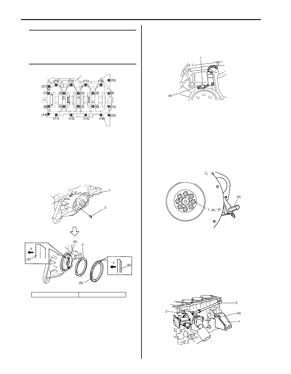
• After tightening crankcase bolts, check to 

be sure that crankshaft rotates smoothly 
when turned by hand.

• Use new crankcase bolt (10 mm thread 

diameter).


9) Pull out dowel pin (2) from crankshaft (1) and then 

install rear oil seal (3) by using special tools and 
plastic hammer.

Special tool
(A):  09911–97710
(B):  09911–97811

10) Install dowel pin (2).

11) Install CKP sensor (1) and fix its wire harness with 

bracket.

Tightening torque
CKP sensor bolt (a):  11 N·m (1.1 kgf-m, 8.0 lb-ft)

12) Install flywheel (drive plate for A/T).

Using special tool, lock flywheel or drive plate, and 
tighten flywheel or drive plate bolts (1) applied with 
sealant to specification.

Special tool
(A):  09924–17810

Tightening torque
Flywheel bolt (a):  70 N·m (7.0 kgf-m, 51.0 lb-ft)
Drive plate bolt:  65 N·m (6.5 kgf-m, 47.0 lb-ft)

13) Install engine front mounting brackets (1). Tighten 

bracket bolts to specified torque.

Tightening torque
Engine front mounting bracket bolt (a):  55 N·m (
5.5 kgf-m, 40.0 lb-ft)

14) Install water pump (2) and heater outlet pipe (3). 

Refer to “Water Pump Removal and Installation (For 
J20 Engine Model): For Petrol Engine Model in 
Section 1F”.

4. Crankshaft side

5. Oil seal side

1

I4RH01140046-01

I5JB0A142058-01

I2RH01140179-01

I2RH01140180-01

I2RH01140181-01

Engine Mechanical: For J20 Engine 1D-123

15) Install pistons and connecting rods. Refer to 

“Pistons, Piston Rings, Connecting Rods and 
Cylinders Removal and Installation: For J20 Engine”.

16) Install oil pump. Refer to “Oil Pump Removal and 

Installation: For J20 Engine in Section 1E”.

17) Install cylinder head assembly to cylinder. Refer to 

“Valves and Cylinder Head Removal and Installation: 
For J20 Engine”.

18) Install, timing chain sprockets, timing chains, timing 

chain tensioner, tensioner adjusters, timing chain 
guides, timing chain cover, crankshaft pulley, water 
pump pulley. Refer to “Timing Chain Cover Removal 
and Installation: For J20 Engine”, 
“2nd Timing Chain 
and Chain Tensioner Removal and Installation: For 
J20 Engine” an
d “1st Timing Chain and Chain 
Tensioner Removal and Installation: For J20 
Engine”.

19) Install oil pump strainer and oil pan referring to “Oil 

Pan and Oil Pump Strainer Removal and Installation: 
For J20 Engine in Section 1E”.

20) Install clutch to flywheel (for M/T vehicle). For clutch 

installation, refer to “Clutch Cover, Clutch Disc and 
Flywheel Removal and Installation in Section 5C”
.

21) Install engine assembly to vehicle. Refer to “Engine 

Assembly Removal and Installation: For J20 
Engine”.

Main Bearings, Crankshaft and Cylinder Block 
Inspection

S6JB0A1426036

Crankshaft
Crankshaft runout
Using a dial gauge, measure runout at center journal. 
Rotate crankshaft slowly. If runout exceeds its limit, 
replace crankshaft.

Limit on runout
0.06 mm (0.0023 in.)

Crankshaft thrust play
Measure this play with crankshaft set in cylinder block in 
the normal manner, that is, with thrust bearing and lower 
crankcase installed. Tighten crankcase bolts referring to 
“Main Bearings, Crankshaft and Cylinder Block Removal 
and Installation: For J20 Engine”.
Use a dial gauge to read displacement in axial (thrust) 
direction of crankshaft.
If its limit is exceeded, replace thrust bearing with new 
standard one or oversize one to obtain standard thrust 
play.

Crankshaft Thrust Play
Standard: 0.10 – 0.35 mm (0.0039 – 0.0137 in.)
Limit: 0.42 mm (0.0149 in.)

Thickness of crankshaft thrust bearing

I2RH01140182-01

Standard

2.500 mm (0.0984 in.)

Oversize: 0.125 mm 

(0.0049 in.)

2.563 mm (0.1009 in.)

1. Thrust bearing

2. Oil groove

I2RH01140183-01

I2RH01140184-01

1D-124 Engine Mechanical: For J20 Engine

Out-of-round and taper (uneven wear) of journals
An unevenly worn crankshaft journal shows up as a 
difference in diameter at a cross section or along its 
length (or both). This difference, if any, is determined by 
taking micrometer readings. If any one of journals is 
badly damaged or if amount of uneven wear in the sense 
exceeds its limit, regrind or replace crankshaft.

Limit on out-of-round and taper
0.01 mm (0.0004 in.)

Out-of-round
“A” – “B”

Taper
“a” – “b”

Main Bearings
Main bearings general information
• Service main bearings are available in standard size 

and 0.25 mm (0.0098 in.) undersize, and standard 
size has 5 kinds of bearings differing in tolerance.

• Upper half of bearing (1) has oil groove (2) as shown 

in figure.
Install this half with oil groove to cylinder block.

• Lower half of bearing does not have oil groove.

Main bearings inspection
Check bearings for pitting, scratches, wear or damage. 
If any malcondition is found, replace both upper and 
lower halves. Never replace either half without replacing 
the other half.

Main bearing clearance
Check clearance by using gauging plastic according to 
the following procedure.

1) Remove lower crankcase.
2) Clean bearings and main journals.
3) Place a piece of gauging plastic (1) to full width of 

bearing (parallel to crankshaft) on journal, avoiding 
oil hole.

4) Install lower crankcase to cylinder block referring to 

“Main Bearings, Crankshaft and Cylinder Block 
Removal and Installation: For J20 Engine”.

NOTE
Do not rotate crankshaft while gauging 
plastic is installed.


5) Remove lower crankcase and using scale (2) on 

gauging plastic envelop (1), measure gauging plastic 
width at its widest point. If clearance exceeds its 
limit, replace bearing. Always replace both upper 
and lower inserts as a unit.
A new standard bearing may produce proper 
clearance. If not, it will be necessary to regrind 
crankshaft journal for use of 0.25 mm undersize 
bearing.
After selecting new bearing, recheck clearance.

Main Bearing Clearance
Standard: 0.032 – 0.050 mm (0.0013 – 0.0019 in.)
Limit: 0.063 mm (0.0024 in.)

I2RH01140185-01

I2RH01140186-01

I2RH01140187-01

I2RH01140188-01

Engine Mechanical: For J20 Engine 1D-125

Selection of main bearings
STANDARD BEARING:
If engine is under the following conditions, select a new 
standard bearing as followings and install it.
• Bearing is in malcondition.
• Bearing clearance is cut of specification.
• Crankshaft or cylinder block is replaced.

1) First check journal diameter. As shown in figure, 

crank web No.2 has stamped numbers.
Six kinds of numbers (“4” through “9”) represent the 
following journal diameters.

Journal diameter

Stamped numbers on crank web No.2 (3) represent 
journal diameters marked with an arrow in figure 
respectively. For example, stamped number “5” 
indicates that corresponding journal diameter is 
58.0000 – 58.0029 mm (2.28346 – 2.28357 in.).

2) Next, check journal bore diameter. On lower 

crankcase five alphabets are stamped as shown in 
figure.
Three kinds of alphabets (“A”, “B” and “C”) represent 
the following journal bore diameters.

Journal bore diameter

Stamped alphabets on lower crankcase represent 
journal diameter marked with an arrow in figure 
respectively.
For example, stamped alphabet “A” at No.2 journal 
indicates that (journal) bore diameter of No.2 journal 
is 62.0000 – 62.0060 mm (2.44094 – 2.44117 in.).

3) There are 5 kinds of standard bearings differing in 

thickness. To distinguish them, they are painted (1) 
in the following colors at the position as indicated in 
figure.
Each color indicates the following thickness at the 
center of bearing.

Standard size main bearing thickness

Stamped numbers

Journal diameter

4

58.0030 – 58.0060 mm 
(2.28358 – 2.28369 in.)

5

58.0000 – 58.0029 mm 
(2.28346 – 2.28357 in.)

6

57.9970 – 57.9999 mm 
(2.28334 – 2.28345 in.)

7

57.9940 – 57.9969 mm 
(2.28323 – 2.28333 in.)

8

57.9910 – 57.9939 mm 
(2.28311 – 2.28322 in.)

9

57.9880 – 57.9909 mm 
(2.28299 – 2.28310 in.)

1. Crankshaft pulley side

2. Flywheel side

Stamped alphabet

Journal bore diameter

A

62.0000 – 62.0060 mm 
(2.44094 – 2.44117 in.)

B

62.0061 – 62.0120 mm 
(2.44118 – 2.44141 in.)

C

62.0121 – 62.0180 mm 
(2.44142 – 2.44164 in.)

1

2

3

I4RH01140047-01

1. No.1 journal

5. No.5 journal

2. No.2 journal

6. Crankshaft pulley side

3. No.3 journal

7. Flywheel side

4. No.4 journal

Color painted

Bearing thickness

Green

1.9910 – 1.9940 mm 

(0.07839 – 0.07850 in.)

Black

1.9940 – 1.9970 mm 

(0.07851 – 0.07862 in.)

Colorless (no painted)

1.9970 – 2.0000 mm 

(0.07863 – 0.07874 in.)

Yellow

2.0000 – 2.0030 mm 

(0.07874 – 0.07885 in.)

Blue

2.0030 – 2.0060 mm 

(0.07886 – 0.07897 in.)

6

7

2

3

4

5

1

I4RH01140048-01

I2RH01140191-01


Content   ..  147  148  149  150   ..