Suzuki Grand Vitara JB416 / JB420 / JB419. Service manual - part 121
 

  Index      Suzuki     Suzuki Grand Vitara JB416 / JB420 / JB419 - service and repair manual 2007 year


Search            copyright infringement  


Content   ..  119  120  121  122   ..


Suzuki Grand Vitara JB416 / JB420 / JB419. Service manual - part 121


1D-10 Engine Mechanical: For M16A Engine with VVT

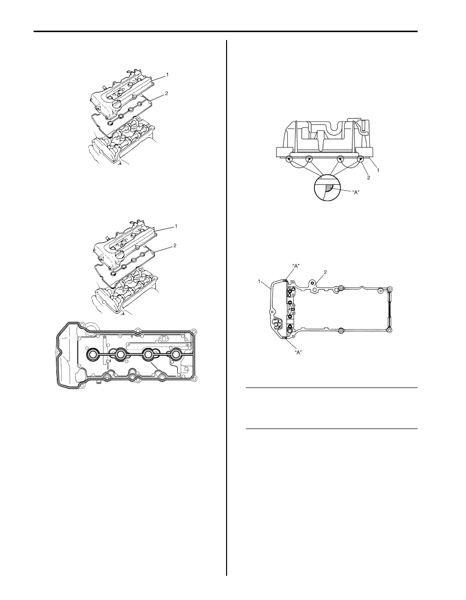
11) Remove cylinder head cover (1) with cylinder head 

cover gasket (2).

Installation

1) Install new cylinder head cover gasket (2) to cylinder 

head cover (1) as shown in the figure.

2) Remove oil, old sealant, and dust from sealing 

surfaces on cylinder head and cover. After cleaning, 
apply sealant “A” to the following point.
• Cylinder head cover gasket (1) sealing surface 

area (2) as shown.

“A”:  Water tight sealant 99000–31250 
(SUZUKI Bond No.1207F) 

• Timing chain cover (1) and cylinder head (2) 

mating surface as shown.

“A”:  Water tight sealant 99000–31250 
(SUZUKI Bond No.1207F) 

3) Install cylinder head cover to cylinder head.

NOTE
When installing cylinder head cover, use care 
so that cylinder head cover gasket or spark 
plug hole gaskets will not get out of place or 
fall off.


4) Tightening bolts in such order as indicated in the 

figure a little at a time till they are tightened to 
specified torque.

Tightening torque
Cylinder head cover bolt (a):  8 N·m (0.8 kgf-m, 
6.0 lb-ft)

I6RS0B141004-01

I6RS0B141005-01

I2RH0B140036-01

I2RH0B140037-01

Engine Mechanical: For M16A Engine with VVT 1D-11

5) Connect PCV hose (2) to PCV valve (3).
6) Connect breather hose (4).
7) Install oil level gauge (1).

8) Install wire harness clamp to cylinder head cover.
9) Install ignition coil assemblies with high-tension cord.

10) Connect ignition coil couplers and clamp harness 

securely.

11) Install cylinder head upper cover.

12) Connect negative cable at battery.

Throttle Body and Intake Manifold Components

S6JB0A1416004

I5JB0A141007-01

I5JB0A141005-05

[A]: Installing location of intake manifold bolt and nut

7. EVAP canister purge valve

14. Intake manifold bolt (short)

1. Intake manifold

8. EVAP canister purge valve hose

15. Intake manifold bolt (long)

2. Gasket

9. MAP sensor bolt

16. To delivery pipe

3. Electrical throttle body

10. To EGR valve

: 5 N

⋅m (0.5 kgf-m, 4.0 lb-ft)

4. EGR pipe

11. To PCV valve

: Do not reuse.

5. MAP sensor

12. To brake booster

6. PCV hose

13. Intake manifold nut

1D-12 Engine Mechanical: For M16A Engine with VVT

Throttle Body On-Vehicle Inspection

S6JB0A1416005

Check electric throttle body assembly referring to “Throttle Valve Operation Check” and “Electric Throttle Body 
Assembly Operation Check” under “Electric Throttle Body Assembly On-Vehicle Inspection: For Petrol Engine Model 
in Section 1C”.

Electric Throttle Body Assembly Removal and 
Installation

S6JB0A1416006

Removal

1) Disconnect negative cable at battery.
2) Drain coolant referring to “Cooling System Draining: 

For Petrol Engine Model in Section 1F”.

3) Detach breather union (1) from air intake pipe (2).
4) Disconnect air intake pipe (2).

5) Disconnect engine coolant hoses (1) from electric 

throttle body assembly (3).

6) Disconnect connector (2) from electric throttle body 

assembly.

7) Remove electric throttle body assembly from intake 

manifold.

Installation

1) Clean mating surfaces and install new throttle body 

gasket to intake manifold.

2) Install electric throttle body assembly (1) to intake 

manifold.

3) Connect connector (2) to electric throttle body 

assembly securely.

4) Connect engine coolant hoses (3) to electric throttle 

body assembly (1).

5) Connect air intake pipe (1) and breather union (2).
6) Tighten air intake pipe bolt (3) to specified torque.

Tightening torque
Air intake pipe bolt (a):  3 N·m (0.3 kgf-m, 2.5 lb-
ft)

7) Refill coolant referring to “Cooling System Flush and 

Refill: For Petrol Engine Model in Section 1F”.

8) Connect negative cable at battery.
9) Perform calibration of electric throttle body assembly 

referring to “Electric Throttle Body System 
Calibration: For Petrol Engine Model in Section 1C” if 
replaced.

1

2

I5JB0A141008-03

3

2

1

I5JB0A141009-02

1

2

3

I5JB0A141010-02

2

1

3, (a)

I5JB0A141011-03

Engine Mechanical: For M16A Engine with VVT 1D-13

Throttle Body Cleaning

S6JB0A1416007

Clean electric throttle body assembly referring to 
“Throttle Valve Visual Check” under “Electric Throttle 
Body Assembly On-Vehicle Inspection: For Petrol 
Engine Model in Section 1C”
.

Intake Manifold Removal and Installation

S6JB0A1416008

Removal

1) Relieve fuel pressure in fuel feed line referring to 

“Fuel Pressure Relief Procedure: For Petrol Engine 
Model in Section 1G”.

2) Remove throttle body referring to “Electric Throttle 

Body Assembly Removal and Installation: For M16A 
Engine with VVT”.

3) Disconnect the following hoses:

• Brake booster hose (2) from intake manifold
• PCV hose (3) from intake manifold
• EVAP canister purge hose (4) from intake 

manifold

• Vacuum hose (5) from intake manifold
• Water No.1 hose (9) from intake manifold
• Water No.2 hose (10) from intake manifold

4) Disconnect the following electric wires:

• Injectors
• Ground terminal (6) from intake manifold
• MAP sensor (1)

5) Remove EVAP canister purge valve (7).
6) Remove intake manifold bracket (8).
7) Remove delivery pipe referring to “Fuel Injector 

Removal and Installation: For Petrol Engine Model in 
Section 1G”.

8) Remove intake manifold (1) and EGR pipe bolt (2) 

from cylinder head, and then remove its gaskets.

Installation
Reverse removal procedure for installation noting the 
followings.
• Use new intake manifold gasket.
• Use new EGR pipe gasket.
• Install intake manifold bolt and nut (1) as shown in 

figure.

• Check to ensure that all removed parts are back in 

place.

• Refill cooling system referring to “Cooling System 

Flush and Refill: For Petrol Engine Model in Section 
1F”.

• Upon completion of installation, turn ignition switch 

ON but engine OFF and check for fuel leaks.

• Finally, start engine and check for engine coolant 

leaks.

6

1

2

5

8

4

7

10

3

9

I5JB0A141012-04

2. Short bolt

3. Long bolt

1

2

I5JB0A141013-02

2

1

2

3

I5JB0A141014-02


Content   ..  119  120  121  122   ..