Suzuki Grand Vitara JB416 / JB420 / JB419. Service manual - part 110
 

  Index      Suzuki     Suzuki Grand Vitara JB416 / JB420 / JB419 - service and repair manual 2007 year


Search            copyright infringement  


Content   ..  108  109  110  111   ..


Suzuki Grand Vitara JB416 / JB420 / JB419. Service manual - part 110


1B-10 Aux. Emission Control Devices: For Diesel Engine Model

Exhaust Gas Temperature Sensor 1, 2 and 3 
Inspection

S6JB0A1226008

NOTE
Exhaust gas temperature sensor 2 and 3 are 
equipped with only vehicle with diesel 
particulate filter.


1) Disconnect negative (–) cable at battery.
2) Disconnect exhaust gas temperature sensor 1, 2 

and/or 3 connectors.

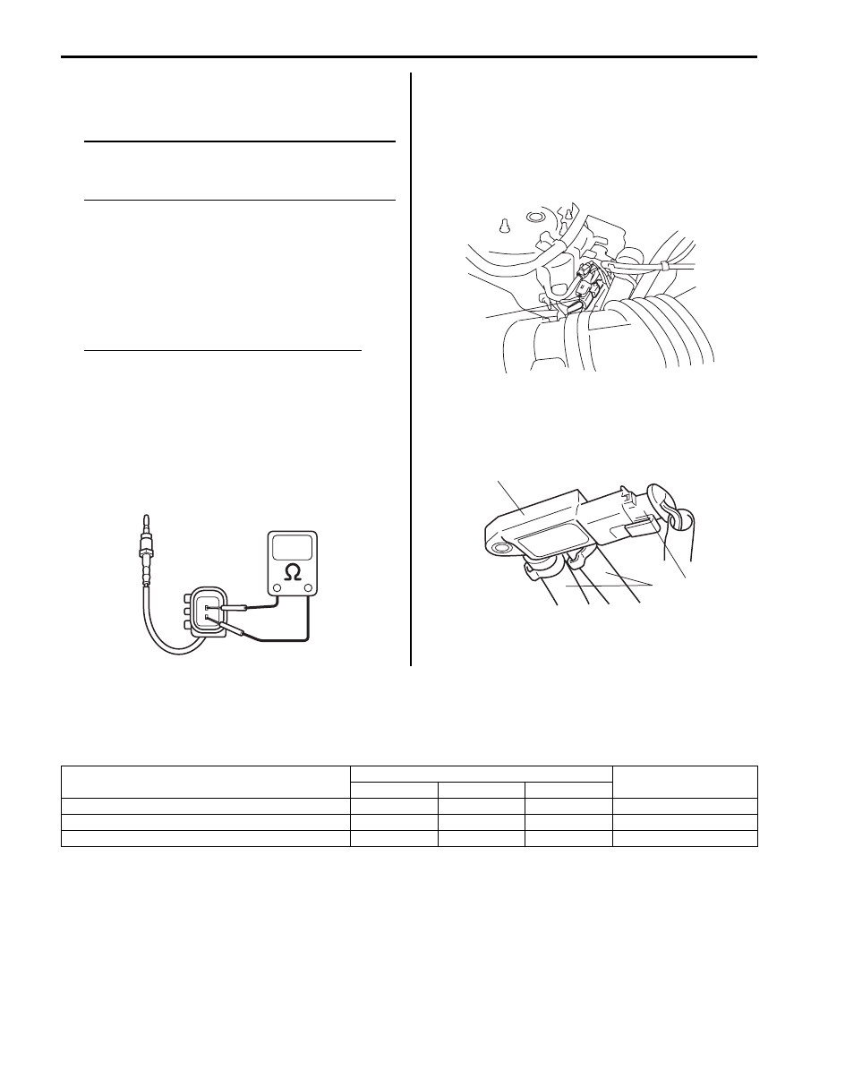
3) Measure resistance between terminals of exhaust 

gas temperature sensor 1, 2 and/or 3 connectors.
If resistance is out of specification, replace exhaust 
gas temperature sensor 1, 2 and/or 3.

Exhaust gas temperature sensor resistance
Exhaust gas temperature sensor 1
1.77 k

 at 400 °C, 752 °F

0.7 k

 at 500 °C, 932 °F

Exhaust gas temperature sensor 2
106 k

 at 50 °C, 122 °F

33.5 k

 at 100 °C, 212 °F

Exhaust gas temperature sensor 3
132 k

 at 250 °C, 482 °F

3.5 k

 at 500 °C, 932 °F

Differential Pressure Sensor Removal and 
Installation (with Diesel Particulate Filter)

S6JB0A1226009

Removal

1) Disconnect negative (–) cable at battery.
2) Detach diesel particulate filter differential pressure 

sensor (1) from its bracket.

3) Disconnect diesel particulate filter differential 

pressure sensor connector (1) and hoses (2) from 
diesel particulate filter differential pressure sensor 
(3).

Installation
Reverse removal procedure of installation.

Specifications

Tightening Torque Specifications

S6JB0A1227001

Reference:
For the tightening torque of fastener not specified in this section, refer to “Fastener Information in Section 0A”.

I5JB0B120014-01

1

I5JB0B120015-01

3

1

2

I5JB0B120016-01

Fastening part

Tightening torque

Note

N

m

kgf-m

lb-ft

Exhaust gas temperature sensor 1

40

4.0 

29.0

)

Exhaust gas temperature sensor 2

30

3.0 

22.0

)

Exhaust gas temperature sensor 3

30

3.0 

22.0

)

Engine Electrical Devices: For Petrol Engine Model 1C-1

Engine

Engine Electrical Devices

For Petrol Engine Model

Repair Instructions

Engine Control Module (ECM) Removal and 
Installation

S6JB0A1316001

CAUTION

!


As ECM consists of precision parts, be 
careful not to expose it to excessive shock.


Removal

1) Disconnect negative cable at battery.
2) Remove ECM cover.
3) Disconnect connectors from ECM as follows.

a) Push lock (1) to release locking of lock lever (2).
b) Turn lock lever to arrow direction until it stops.

4) Remove ECM (1) from its bracket by removing its 

mounting bolts (2).

Installation
Reverse removal procedure noting the following:
• Connect connectors to ECM as follows.

a. Make sure that lock lever of ECM connector is 

unlock position.

b. Insert ECM connectors to ECM until it stops with 

unlocked lock lever.

c. Lock ECM connectors securely by pulling its lock 

lever up.

1

2

I4RS0A130003-01

1

2

2

2

I5JB0A130012-03

I4RS0B130021-01

I4RS0B130022-01

I4RS0A130004-01

1C-2 Engine Electrical Devices: For Petrol Engine Model

Manifold Absolute Pressure (MAP) Sensor 
Inspection

S6JB0A1316002

1) Disconnect connector from MAP sensor.
2) Remove MAP sensor from intake manifold.
3) Arrange 3 new 1.5 V batteries (2) in series (check 

that total voltage is 4.5 – 5.0 V) and connect its 
positive terminal to “Vin” terminal of sensor and 
negative terminal to “Ground” terminal. Then check 
voltage between “Vout” and “Ground”. Also, check if 
voltage reduces when vacuum is applied up to 400 
mmHg by using vacuum pump (3).
If check result is not satisfactory, replace MAP 
sensor (1).

Output voltage (When input voltage is 4.5 – 5.5 V, 
ambient temp. 20 – 30 

°C, 68 – 86 °F)

4) Install MAP sensor securely.
5) Connect MAP sensor connector securely.

Electric Throttle Body Assembly On-Vehicle 
Inspection

S6JB0A1316003

WARNING

!


Never touch throttle valve with finger while 
ignition switch is turned ON and accelerator 
pedal is depressed. Otherwise, injury may 
result by pinching the finger between throttle 
valve and throttle body housing.


CAUTION

!


• Do not disassemble electric throttle body 

assembly.

• Do not expose electric throttle body 

assembly to excessive shock like a 
dropping it. If electric throttle body 
assembly has been exposed to excessive 
shock, it should be replaced.

• Be careful not to accrete a foreign material 

(like dust and/or metallic particle) to the 
throttle body housing and/or throttle valve.
Otherwise, the throttle body assembly is 
breaking down by throttle valve accretion.

• Do not apply excessive moving force to 

throttle valve for throttle valve operation 
check and/or TP sensor performance 
check.
Otherwise, the throttle body assembly is 
breaking down by damaging the internal 
resinous gear of throttle valve actuator.


Throttle Valve Visual Check

1) Remove air cleaner outlet hose (for J20 engine) or 

air intake pipe (for M16 engine).

2) Check that there isn’t any foreign matter caught 

between throttle valve and throttle body housing. If 
there is, take it out after removing throttle body 
referring to “Electric Throttle Body Assembly 
Removal and Installation: For J20 Engine in Section 
1D” 
or “Electric Throttle Body Assembly Removal 
and Installation: For M16A Engine with VVT in 
Section 1D”a
nd clean inside of throttle body 
thoroughly.

Altitude 

(Reference)

Barometric pressure

Output 

voltage

(ft)

(m)

(mmHg)

(kPa)

(V)

0 – 2000

0 – 610

760 – 707 100 – 94 3.3 – 4.3

2001 – 

5000

611 – 

1524

Under 707

over 634

94 – 85

3.0 – 4.1

5001 – 

8000

1525 – 

2438

Under 634

over 567

85 – 76

2.7 – 3.7

8001 – 

10000

2439 – 

3048

Under 567

over 526

76 – 70

2.5 – 3.3

4. Voltmeter

I3RM0A130005-01

Engine Electrical Devices: For Petrol Engine Model 1C-3

Throttle Valve Operation Check

1) Remove air cleaner outlet hose (for J20 engine) or 

air intake pipe (for M16 engine).

2) Turn OFF ignition switch.
3) Move throttle valve with finger to its full open position 

and check that it moves smoothly.

4) Move throttle valve with finger to its completely 

closed position and check that it moves smoothly.

5) Take off finger from throttle valve (1) which is at full 

open position and check that it moves smoothly by 
its return spring and open spring force back to 
default position (position where throttle valve is open 
by 7

° (2) from completely closed position).

6) Take off finger from throttle valve (1) which is at 

completely closed position and check that it moves 
smoothly by its return spring and open spring force 
back to default position.

If check result is not satisfactory, replace electric 
throttle body assembly.

Electric Throttle Body Assembly Operation Check

1) Remove air cleaner outlet hose (for J20 engine) or 

air intake pipe (for M16 engine).

2) Turn ON ignition switch.
3) Depress accelerator pedal gradually and check that 

throttle valve moves smoothly until it opens fully.

4) Release accelerator pedal depressed in Step 3) and 

check that throttle valve (1) moves back to default 
position (position where throttle valve is open by 7

° 

(2) from its completely closed position).

If check result is satisfactory, electric throttle body 
system is in good condition. If check result is not 
satisfactory, proceed to next step.

5) Perform “Accelerator Pedal Position (APP) Sensor 

Assembly On-Vehicle Inspection”, “Throttle Actuator 
(Motor) Check” and “Throttle Position Sensor 
Performance Check”.
If check results are not satisfactory, replace electric 
throttle body assembly.
If check results are satisfactory, wire circuit and/or 
ECM are faulty.

Throttle Actuator (Motor) Check

1) Turn OFF ignition switch.
2) Disconnect connector from electric throttle body 

assembly.

3) Measure resistance between “M1” terminal (1) and 

“M2” terminal (2) of electric throttle body assembly.
If measured resistance is out of specified value, 
replace electric throttle body assembly.

Throttle actuator (motor) resistance
0.3 – 100 

 at 20 °C, 68 °F

I5JB0A130013-01

1

2

I5JB0A130035-01

[A]: For J20 engine
[B]: For M16 engine

1

2

I5JB0A130035-01

1

2

1

2

[B]

[A]

I5JB0A130014-01


Content   ..  108  109  110  111   ..