Suzuki Grand Vitara JB416 / JB420 / JB419. Service manual - part 74
1A-243 Engine General Information and Diagnosis: For Petrol Engine Model
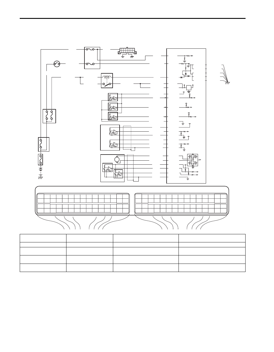
ECM Power and Ground Circuit Check
S6JB0A1114081
Wiring Diagram
E23
C37
3
4
18
19
5
6
7
10
11
17
20
47
46
49
50
51
21
22
52
16
25
9
24
14
29
55
57
54 53
59
60
58
2
26
27
28
15
30
56
48
32
31
34
35
36
37
40
42
39 38
44
45
43
41
33
1
12
13
23
8
3
4
18
19
5
6
7
10
11
17
20
47
46
49
50
51
21
22
52
16
25
9
24
14
29
55
57
54 53
59
60
58
2
26
27
28
15
30
56
48
32
31
34
35
36
37
40
42
39 38
44
45
43
41
33
1
12
13
23
8
BLK/WHT
BLU/BLK
BLU/BLK
BLU/BLK
BLK/RED
BLK/RED
BLK/RED
BLK/YEL
BLU
12V
5V
2
1
3
12
13
14-1
15-1
15-2
14-2
4
6
E23-29
E23-1
E23-60
E23-16
9
10
11
WHT
E23-2
WHT/GRN
GRY/RED
BLU
RED/WHT
GRY/GRN
C37-14
C37-9
C37-55
C37-57
GRY/BLK
C37-12
E23-55
BLU/YEL
BLU/RED
C37-45
C37-44
5
C37-15
C37-29
C37-48
BLK/ORN
C37-58
C37-30 BLK/ORN
BLK/YEL
BLK/YEL
BLK/YEL
E23-56
E23-54
E23-53
E23-52
E23-51
C37-53
C37-54
C37-40
C37-41
WHT/BLU
WHT
ORN
ORN/BLU
BLU/GRN
BLU/YEL
WHT
BLK
RED
GRN
WHT
WHT
8
7
I5JB0A110096-01
1. Fuse box No.2
6. ECM
11. Electric load current sensor (for J20
engine)
15-1. TP sensor (main)
2. Ignition switch
7. “IG ACC” fuse
12. MAP sensor
15-2. TP sensor (sub) (for AMT model)
3. Main relay
8. “FI” fuse
13. A/C refrigerant pressure sensor (if
equipped with A/C)
4. Junction block
9. “DOME” fuse
14-1. Accelerator pedal position (APP)
sensor (main)
5. “IG COIL” fuse
10. DLC
14-2. Accelerator pedal position (APP)
sensor (sub)