Suzuki Grand Vitara JB416 / JB420 / JB419. Service manual - part 52
 

  Index      Suzuki     Suzuki Grand Vitara JB416 / JB420 / JB419 - service and repair manual 2007 year


Search            copyright infringement  


Content   ..  50  51  52  53   ..


Suzuki Grand Vitara JB416 / JB420 / JB419. Service manual - part 52


1A-155 Engine General Information and Diagnosis: For Petrol Engine Model

12 Wire circuit check

1) Measure voltage between “RED” wire terminal of 

radiator cooling fan relay No.2 connector and vehicle 
body ground with ignition switch turned ON.

Is voltage 0 V?

Go to Step 13.

“RED” wire is shorted to 
other circuit.

13 Wire circuit check

1) Measure resistance between “RED” wire terminal of 

radiator cooling fan relay No.2 connector and “E23-47” 
terminal of ECM connector with ignition switch turned 
OFF.

Is resistance below 2 

?

Go to Step 20.

“RED” wire is open 
circuit.

14 Wire circuit check

1) Disconnect connectors from ECM with ignition switch 

turned OFF.

2) Measure voltage between “E23-48” terminal of ECM 

connector and vehicle body ground with ignition switch 
turned ON.

Is voltage 10 – 14 V?

Go to Step 15.

Go to Step 16.

15 Radiator cooling fan control No.3 check

1) Connect connectors to ECM with ignition switch turned 

OFF.

2) Run engine until ECT is over 102.5 

°C, 216.5 °F.

3) Measure voltage between “E23-48” terminal of ECM 

connector and vehicle body ground.

Is voltage below 1.5 V?

Intermittent trouble.
Check for intermittent 
referring to “Intermittent 
and Poor Connection 
Inspection in Section 
00”.

Substitute a known-
good ECM and recheck.

16 Wire circuit check

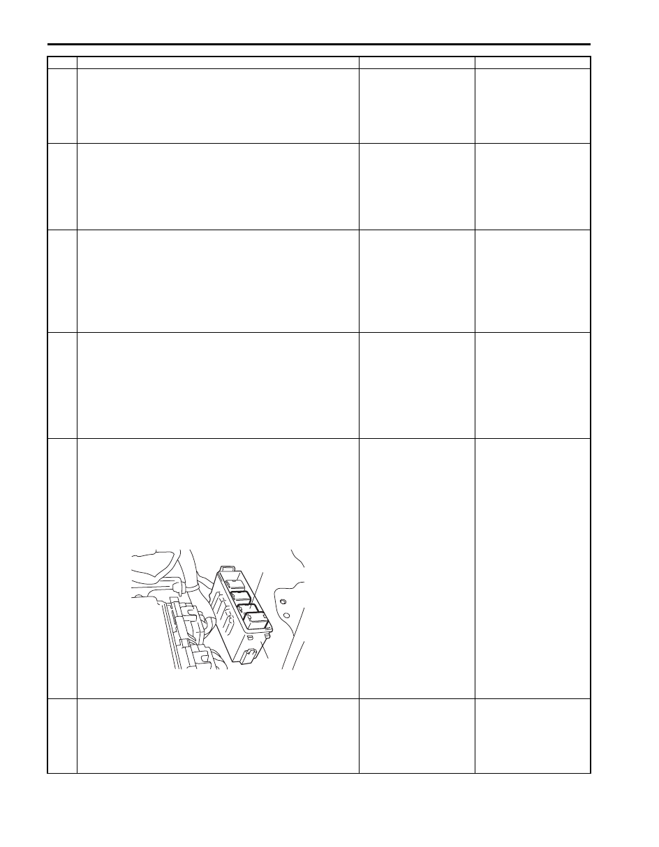
1) Disconnect radiator cooling fan relay No.3 (1) from relay 

box (2) with ignition switch turned OFF.

2) Turn ON ignition switch.
3) Measure voltage between “YEL/GRN” wire terminal of 

radiator cooling fan relay No.3 connector and vehicle 
body ground.

Is voltage 10 – 14 V?

Go to Step 17.

“YEL/GRN” wire is open 
circuit.

17 Wire circuit check

1) Measure resistance between “RED/YEL” wire terminal of 

radiator cooling fan relay No.3 connector and vehicle 
body ground with ignition switch turned OFF.

Is resistance infinity?

Go to Step 18.

“RED/YEL” wire is 
shorted to ground 
circuit.

Step

Action

Yes

No

1

2

I5JB0A110059-02

Engine General Information and Diagnosis: For Petrol Engine Model 1A-156

DTC P0500: Vehicle Speed Sensor (VSS) Malfunction

S6JB0A1114051

Wiring Diagram

DTC Detecting Condition and Trouble Area

18 Wire circuit check

1) Measure voltage between “RED/YEL” wire terminal of 

radiator cooling fan relay No.3 connector and vehicle 
body ground with ignition switch turned ON.

Is voltage 0 V?

Go to Step 19.

“RED/YEL” wire is 
shorted to other circuit.

19 Wire circuit check

1) Measure resistance between “RED/YEL” wire terminal of 

radiator cooling fan relay No.3 connector and “E23-48” 
terminal of ECM connector with ignition switch turned 
OFF.

Is resistance below 5 

?

Go to Step 20.

“RED/YEL” wire is open 
circuit

20 Radiator cooling fan relay check

1) Check radiator cooling fan relay referring to “Radiator 

Cooling Fan Relay Inspection: For Petrol Engine Model 
in Section 1F”.

Is it in good condition?

Substitute a known-
good ECM and recheck.

Replace relay.

Step

Action

Yes

No

E23-4

E23-19

WHT/RED

WHT/BLU

WHT/RED

WHT/BLU

E23

C37

3

4

18

19

5

6

7

10

11

17

20

47

46

49

50

51

21

22

52

16

25

9

24

14
29

55

57

54 53

59

60

58

2

26

27

28

15
30

56

48

32

31

34

35

36

37

40

42

39 38

44

45

43

41

33

1

12

13

23

8

3

4

18

19

5

6

7

10

11

17

20

47

46

49

50

51

21

22

52

16

25

9

24

14
29

55

57

54 53

59

60

58

2

26

27

28

15
30

56

48

32

31

34

35

36

37

40

42

39 38

44

45

43

41

33

1

12

13

23

8

BLK

WHT

BLK

WHT

YEL/BLK

YEL

LT GRN
LT GRN/BLK

12V

12V

1

2

3

4

I5JB0A110060-03

1. Rear left side wheel speed sensor (VSS 1)

3. ABS / ESP

® control module 

2. Rear right side wheel speed sensor (VSS 2)

4. ECM

DTC detecting condition

Trouble area

Vehicle speed signal is not input while fuel is cut at 
deceleration for 4 seconds continuously at 3600 rpm or less.
(2 driving cycle detection logic)

• Wheel speed sensor (VSS)
• Wheel speed sensor circuit 
• ABS / ESP

® control module

• ECM

1A-157 Engine General Information and Diagnosis: For Petrol Engine Model

DTC Confirmation Procedure

WARNING

!


• When performing a road test, select a place where there is no traffic or possibility of a traffic 

accident and be very careful during testing to avoid occurrence of an accident.

• Road test should be carried out by 2 persons, a driver and a tester.


1) With ignition switch turned OFF, connect scan tool.
2) Turn ON ignition switch and clear DTC using scan tool.
3) Warm up engine to normal operating temperature.
4) Drive vehicle at 4000 rpm (engine speed) with 3rd gear (for M/T vehicle) or “3” range (for A/T vehicle).
5) Release accelerator pedal and with engine brake applied, keep vehicle coasting for 6 sec. or more (fuel cut 

condition for 5 sec. or more) and stop vehicle.

6) For A/T model, drive vehicle at more than 3700 rpm for 10 sec.
7) Check pending DTC and DTC.

DTC Troubleshooting

NOTE
Before this trouble shooting is performed, read the precautions for DTC troubleshooting referring to 
“Precautions for DTC Troubleshooting: For Petrol Engine Model”.


Step

Action

Yes

No

1

Was “Engine and Emission Control System Check” 
performed?

Go to Step 2.

Go to “Engine and 
Emission Control 
System Check: For 
Petrol Engine Model”
.

2

Vehicle speed signal check

Is vehicle speed displayed on scan tool in Step 4) and 5) of 
“DTC Confirmation Procedure”?

Intermittent trouble.
Check for intermittent 
referring to “Intermittent 
and Poor Connection 
Inspection in Section 
00”.

Go to Step 3.

3

DTC check in ABS / ESP

® control module 

1) Connect scan tool to DLC with ignition switch turned 

OFF.

2) Check ABS / ESP

® control module for DTC.

Is there any DTDC(s) in ABS / ESP

®

 control module?

Go to applicable DTC 
diag. flow.

Substitute a known-
good ECM and recheck.

Engine General Information and Diagnosis: For Petrol Engine Model 1A-158

DTC P0504: Brake Switch “A”/“B” Correlation (For J20 Engine)

S6JB0A1114052

Wiring Diagram

DTC Detecting Condition and Trouble Area

DTC Confirmation Procedure

1) With ignition switch turned OFF, connect scan tool to DLC.
2) Turn ON ignition switch and clear DTC.
3) Start engine and warm up to normal operating temperature. (ECT approx. 90 – 95 

°C, 194 – 203 °F)

4) Drive vehicle at 50 km/h (80 mph) or higher for 3 min. or more.
5) Stop vehicle.
6) Depress brake pedal for 3 times.
7) Check DTC and pending DTC.

E23

C37

3

4

18

19

5

6

7

10

11

17

20

47

46

49

50

51

21

22

52

16

25

9

24

14
29

55

57

54 53

59

60

58

2

26

27

28

15
30

56

48

32

31

34

35

36

37

40

42

39 38

44

45

43

41

33

1

12

13

23

8

3

4

18

19

5

6

7

10

11

17

20

47

46

49

50

51

21

22

52

16

25

9

24

14
29

55

57

54 53

59

60

58

2

26

27

28

15
30

56

48

32

31

34

35

36

37

40

42

39 38

44

45

43

41

33

1

12

13

23

8

BLK/YEL

WHT/GRN

GRN/WHT

E23-20

GRN/WHT

GRN

12V

E23-8

BLU/BLK

WHT

YEL/GRN

1

3

2

4

5

6

7

I5JB0A110107-02

1. Stop lamp (brake pedal) switch

3. Brake pedal switch

5. Stop lamp

7. “STOP” fuse

2. Stop lamp switch

4. ECM

6. “CRUISE” fuse

DTC detecting condition

Trouble area

Brake pedal switch signal is inconsistent with stop lamp 
switch signal.
(1 driving cycle detection logic but MIL does not light up)

• Stop lamp (brake pedal) switch and/or its circuit
• ECM


Content   ..  50  51  52  53   ..