Suzuki Grand Vitara JB416 / JB420 / JB419. Service manual - part 6
 

  Index      Suzuki     Suzuki Grand Vitara JB416 / JB420 / JB419 - service and repair manual 2007 year


Search            copyright infringement  


Content   ..  4  5  6  7   ..


Suzuki Grand Vitara JB416 / JB420 / JB419. Service manual - part 6


General Information:  0A-5

Standard Tightening Torque
Each fastener should be tightened to the torque specified in each section of this manual. If no description or 
specification is provided, refer to the following tightening torque chart for the applicable torque for each fastener. When 
a fastener of greater strength than the original one is used, however, use the torque specified for the original fastener.

NOTE

• For the flanged bolt, flanged nut and self-lock nut of 4T and 7T strength, add 10% to the tightening 

torque given in the following chart.

• The following chart is applicable only where the fastened parts are made of steel light alloy.


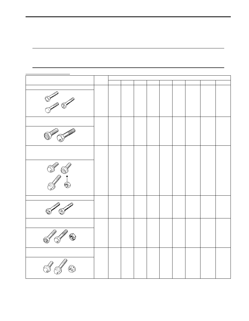
Tightening torque chart

Strength

Unit

Thread Diameter (Nominal Diameter) (mm)

4

5

6

8

10

12

14

16

18

A equivalent of 4T strength fastener

N

m

kgf-m

lb-ft

1.5

0.15

1.0

3.0

0.30

2.5

5.5

0.55

4.0

13

1.3
9.5

29

2.9

21.0

45

4.5

32.5

65

6.5

47.0

105

10.5
76.0

160

16.0

116.0

A equivalent of 6.8 strength 
fastener without flange

N

m

kgf-m

lb-ft

2.4

0.24

2.0

4.7

0.47

3.5

8.4

0.84

6.0

20

2.0

14.5

42

4.2

30.5

80

8.0

58.0

125

12.5
90.5

193

19.3

139.5

280

28.0

202.5

A equivalent of 6.8 strength 
fastener with flange
*: Self-lock nut (6 strength)

N

m

kgf-m

lb-ft

2.4

0.24

2.0

4.9

0.49

3.5

8.8

0.88

6.5

21

2.1

15.5

44

4.4

32.0

84

8.4

61.0

133

13.3
96.5

203

20.3

147.0

298

29.8

215.5

A equivalent of 7T strength fastener

N

m

kgf-m

lb-ft

2.3

0.23

2.0

4.5

0.45

3.5

10

1.0
7.5

23

2.3

17.0

50

5.0

36.5

85

8.5

61.5

135

13.5
98.0

210

21

152.0

240

24

174.0

A equivalent of 8.8 strength bolt (8 
strength nut) without flange

N

m

kgf-m

lb-ft

3.1

0.31

2.5

6.3

0.63

4.5

11

1.1
8.0

27

2.7

19.5

56

5.6

40.5

105

10.5
76.0

168

16.8

121.5

258

25.8

187.0

373

37.3

270.0

A equivalent of 8.8 strength bolt (8 
strength nut) with flange

N

m

kgf-m

lb-ft

3.2

0.32

2.5

6.5

0.65

5.0

12

1.2
9.0

29

2.9

21.0

59

5.9

43.0

113

11.3
82.0

175

17.5

126.5

270

27

195.5

395

39.5

286.0

I1SQ01010004-01

I1SQ01010005-01

I1SQ01010006-01

I1SQ01010007-01

I1SQ01010008-01

I1SQ01010009-01

0A-6 General Information: 

Vehicle Lifting Points

S6JB0A0101005

WARNING

!


• Before applying hoist to underbody, always take vehicle balance throughout service into 

consideration. Vehicle balance on hoist may change depending of what part to be removed.

• Before lifting up the vehicle, check to be sure that end of hoist arm is not in contact with brake pipe, 

fuel pipe, bracket or any other part.

• When using frame contact hoist, apply hoist as shown (right and left at the same position). Lift up 

the vehicle till 4 tires are a little off the ground and make sure that the vehicle will not fall off by 
trying to move vehicle body in both ways. Work can be started only after this confirmation.

• Make absolutely sure to lock hoist after vehicle is hoisted up.


: 1

: 3

: 2

4

I5JB0A010002-02

1. Support position for frame contact hoist (when engine assembly is not removed) and safety stand

3. Floor jack position

2. Support position for frame contact hoist (when engine assembly is removed)

4. Vehicle front

General Information:  0A-7

When using floor jack

WARNING

!


• If the vehicle to be jacked up only at the 

front or rear end, be sure to block the 
wheels on ground in order to ensure 
safety.
After the vehicle is jacked up, be sure to 
support it on stands. It is extremely 
dangerous to do any work on the vehicle 
raised on jack alone.


CAUTION

!


• Never apply jack against engine under 

cover, suspension parts (i.e., stabilizer, 
etc.) or vehicle floor, or it may get 
damaged.


In raising front or rear vehicle end off the floor by jacking, 
be sure to put the jack against the center portion of the 
front suspension frame (1) or rear differential (2).

To perform service with either front or rear vehicle end 
jacked up, be sure to place safety stands (1) under 
chassis frame so that body is securely supported. 
And then check to ensure that chassis frame does not 
slide on safety stands (1) and the vehicle is held stable 
for safety’s sake.

1

2

I5JB0A010003-01

[A]: Front

[B]: Rear

[A]

[B]

1

1

I5JB0A010004-02

0A-8 General Information: 

Engine Supporting Points

S6JB0A0101006

WARNING

!


When using engine supporting device (1), be 
sure to observe the followings.
Otherwise, not only deformation of vehicle 
body and/or engine hook but also personal 
injury may result.
• Apply supporting device at the specified 

positions (2) indicated in figure

• Install supporting device taking a well-

balanced posture.

• Do not contact supporting device with 

other parts than specified positions and 
engine hooks.

• Do not remove engine rear mounting 

(transfer mounting) while supporting.

• Set support device so that side force 

applies to hook excessively.
Excessive side force will deform hook.


Vehicle Identification Number

S6JB0A0101007

The vehicle identification number is punched on the front 
dash panel in engine room and it is also attached on the 
left front top of instrument panel depending on vehicle 
specification.

1

2

2

I5JB0A010005-02

I5JB0A010001-02


Content   ..  4  5  6  7   ..