Suzuki Grand Vitara JB419. Service manual - part 172
 

  Index      Suzuki     Suzuki Grand Vitara JB419 (with F9Q engine) - service and repair manual 2007 year


Search            


Content   ..  170  171  172  173   ..


Suzuki Grand Vitara JB419. Service manual - part 172


Instrumentation / Driver Info. / Horn:  9C-5

Oil Pressure Switch Inspection

S5JB0B9306007

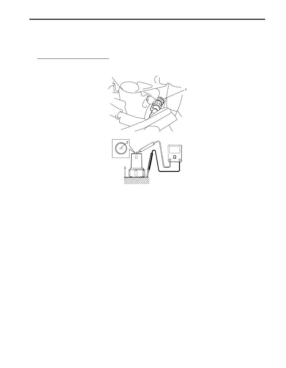
1) Disconnect connector from oil pressure switch (1).
2) Check for continuity between oil pressure switch terminal (2) and cylinder block (3) as shown.

If check result is not as specified, replace oil pressure switch (1).

Oil pressure sensor specification
During engine running: No continuity
At engine stop: Continuity

I5JB0B930004-01

9C-6 Instrumentation / Driver Info. / Horn: 

Table of Contents 10- i

10

Section 10

CONTENTS

Control Systems

Precautions ............................................... 10-*

Precautions............................................................10-*

Precautions for Control Systems.......................... 10-*

Cruise Control System.......................... 10A-1

General Description ...........................................10A-1

Cruise Control System Construction ................. 10A-1
Components and Functions of Cruise Control 

System ............................................................10A-2

Cancel Conditions of Cruise Control System .... 10A-3

Schematic and Routing Diagram......................10A-3

Cruise Control System Input / Output Diagram ..10A-3
Cruise Control System Wiring Diagram ............10A-4

Diagnostic Information and Procedures..........10A-5

Cruise Control System Symptom Diagnosis .....10A-5
Inspection of Cruise Control System Circuit......10A-6

Repair Instructions ............................................ 10A-*

Cruise Control Switch Removal and 

Installation........................................................10A-*

Cruise Control Switch Inspection .......................10A-*
CPP Switch (for Cruise Control) Removal and 

Installation........................................................10A-*

Clutch Pedal Position (CPP) Switch (for 

Cruise Control) Inspection and Adjustment .....10A-*

Stop (Brake) Lamp Switch Removal and 

Installation........................................................10A-*

Stop (Brake) Lamp Switch Inspection ................10A-*
ECM Removal and Installation...........................10A-*

Specifications..................................................... 10A-*

Tightening Torque Specifications.......................10A-*

Body Electrical Control System ........... 10B-1

Precautions.........................................................10B-1

Precautions in Diagnosing Trouble ...................10B-1

General Description ...........................................10B-1

BCM General Description ..................................10B-*

CAN Communication for BCM ..........................10B-1

Schematic and Routing Diagram......................10B-3

Body Electrical Control System Wiring Circuit 

Diagram ..........................................................10B-3

Connector Layout Diagram of BCM ...................10B-*

Component Location .........................................10B-5

BCM and Related System Component 

Location ..........................................................10B-5

Diagnostic Information and Procedures..........10B-6

BCM Self-Diagnosis Function ........................... 10B-*
Body Electrical Control System Check.............. 10B-*

Scan Tool Data .................................................10B-6
DTC Table.........................................................10B-8

DTC Check........................................................ 10B-*
DTC Clearance ................................................. 10B-*
BCM Power Circuit and Ground Circuit Check .. 10B-*
DTC B1133 (DTC No. 1133): Battery Voltage 

Too High.......................................................... 10B-*

DTC B1141 / B1142 / B1143 (No. 1141 / No. 

1142/ No. 1143): Outside Air Temperature 
(Ambient Temp.) Sensor Circuit Malfunction .. 10B-*

DTC B1150 (No. 1150): Air Bag 

Communication Circuit Malfunction................. 10B-*

DTC B1157 (No. 1157): Air Bag Deployment 

Signal Input ..................................................... 10B-*

DTC B1170 (No. 1170): EEPROM access 

error................................................................. 10B-*

DTC U1073 (No. 1073): Control Module 

Communication Bus Off ..................................10B-9

DTC U1100 (No. 1100): Lost Communication 

with ECM.......................................................10B-11

Inspection of BCM and its Circuits .................... 10B-*

Repair Instructions ............................................ 10B-*

BCM Removal and Installation.......................... 10B-*
Outside Air Temperature Sensor Removal 

and Installation ................................................ 10B-*

Outside Air Temperature Sensor Inspection ..... 10B-*

Special Tools and Equipment ........................... 10B-*

Special Tool ...................................................... 10B-*

Immobilizer Control System ................. 10C-1

Precautions.........................................................10C-1

Precautions in Diagnosing Troubles .................10C-1
Precaution in Replacing Immobilizer Control 

Module (ICM) ..................................................10C-1

Precautions in Handling Immobilizer Control 

System ............................................................10C-1

General Description ...........................................10C-2

Immobilizer Control System Introduction ..........10C-2
On-Board Diagnostic System Description 

(Self-diagnosis Function) ................................10C-2

Schematic and Routing Diagram......................10C-3

NOTE
For the items with asterisk (*) in the “CONTENTS” below, refer to the same section of the service manual 
mentioned in the “FOREWORD” of this manual.

10-ii Table of Contents

Immobilizer Control System Wiring Circuit 

Diagram ..........................................................10C-3

Component Location .........................................10C-4

Immobilizer Control System Components 

Location ..........................................................10C-4

Diagnostic Information and Procedures..........10C-5

Immobilizer Control System Check ...................10C-5
Diagnostic Trouble Code (DTC) Check.............10C-6
Diagnostic Trouble Code (DTC) Clearance ......10C-6
Diagnostic Trouble Code (DTC) Table..............10C-6
Scan Tool Data .................................................10C-7
Injection Warning Light Does Not Come ON 

with Ignition Switch ON and Engine Stop .......10C-8

Injection Warning Light Remains ON after 

Engine Start ....................................................10C-9

DTC B1701: Transponder Code Error 1/DTC 

B1710: Transponder Code Error 3..................10C-9

DTC B1702: ECM Communication Error 1 .......10C-9
DTC B1703: Unregistered Transponder .........10C-11
DTC B1704: Transponder Code Error 2 .........10C-11
DTC B1705: Transponder Response Error.....10C-12

DTC B1706: Immobilizer Antenna Error..........10C-12
DTC B1707: IMM EEPROM Error...................10C-13
DTC B1708: ECM Code Error.........................10C-13
DTC B1709: ECM Communication Error 2 .....10C-14
DTC B1711: ECM EEPROM Error..................10C-15
DTC B1712: Immobilizer Communication 

Error ..............................................................10C-15

DTC B1713: Immobilizer Code Error ..............10C-17
DTC B1714: Unregistered Code .....................10C-17
Inspection of Immobilizer Control Module 

(ICM) and Its Circuit ......................................10C-18

Repair Instructions ..........................................10C-20

Immobilizer Control Module (ICM) Removal 

and Installation ..............................................10C-20

Registration of the Ignition Key .......................10C-21
Procedure after ECM Replacement ................10C-21
Procedure after Immobilizer Control Module 

(ICM) Replacement .......................................10C-21

Special Tools and Equipment .........................10C-21

Special Tool ....................................................10C-21


Content   ..  170  171  172  173   ..