Suzuki Grand Vitara JB419. Service manual - part 92
 

  Index      Suzuki     Suzuki Grand Vitara JB419 (with F9Q engine) - service and repair manual 2007 year


Search            


Content   ..  90  91  92  93   ..


Suzuki Grand Vitara JB419. Service manual - part 92


Electronic Stability Program:  4F-1

Brakes

Electronic Stability Program

Precautions

Precautions in Diagnosing Troubles

S5JB0B4600006

To ensure that the trouble diagnosis is done accurately 
and smoothly, observe the following and follow 
“Electronic Stability Program Check”.
• Diagnostic information stored in ESP

® control module 

memory can be cleared as well as checked by using 
SUZUKI scan tool. Before using scan tool, read its 
Operator’s (Instruction) Manual carefully to have good 
understanding as to what functions are available and 
how to use it.

• If the vehicles was operated in any of the following 

ways, ESP

® warning lamp may light momentarily but 

this does not indicate anything abnormal in ESP

®.

– The vehicle was driven with parking brake pulled.
– The vehicle was driven with brake dragging.
– The vehicle was stuck in mud, sand, etc.
– Wheel spin occurred while driving.
– Wheel(s) was rotated while the vehicle was jacked 

up.

• Be sure to read “Precautions for Electrical Circuit 

Service in Section 00 in related manual” before 
inspection and observe what is written there.

• Be sure to use the trouble diagnosis procedure as 

described in “Electronic Stability Program Check”. 
Failure to follow it may result in incorrect diagnosis. 
(Some other diagnosis trouble code may be stored by 
mistake in the memory of ESP

® control module 

during inspection.)

• When disconnecting ESP

® control module connector 

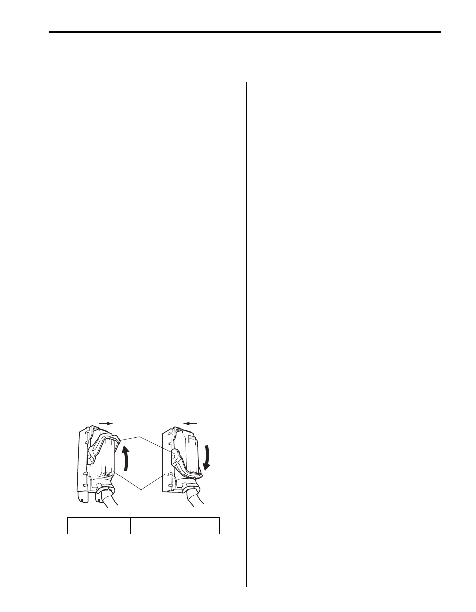
(1), pull up lock lever (2) of connector.
When connecting, set the connector on ESP

® 

hydraulic unit / control module assembly and pull 
down the lock lever (2) until it locks.

• Communication of ECM, BCM, ESP

® (ABS) control 

module (if equipped), 4WD control module (if 
equipped), immobilizer control module (ICM) (if 
equipped), combination meter and steering angle 
sensor (if equipped) is established by CAN (Controller 
Area Network).
Therefore, be sure to read “Precaution for CAN 
Communication System in Section 00 in related 
manual” before inspection and handling CAN 
communication line.

Precautions in On-Vehicle Service

S5JB0B4600007

When connector is connected to ESP

® hydraulic unit / 

control module assembly, do not disconnect connectors 
of sensors with ignition switch ON. Otherwise, DTC will 
be set in ESP

® control module.

Precautions in Hydraulic Unit Operation Check

S5JB0B4600008

ESP

® hydraulic unit / control module assembly function 

is checked by correct wheel lock / release condition 
when brake pressure is pressurized / depressurized 
using SUZUKI scan tool. The hydraulic unit operation 
check referring to “Hydraulic Unit Operation Check in 
Section 4E” sho
uld be performed to confirm the correct 
brake pipe connection in the following cases.
• ESP

® hydraulic unit / control module assembly was 

replaced.

• Brake pipe and/or hose were replaced.

[A]: Disconnect

C: Pull up to disconnect

[B]: Connect

D: Pull down to connect

2

1

[A]

[B]

C

D

I6JB01460001-01

4F-2 Electronic Stability Program: 

Precautions in Sensor Calibration

S5JB0B4600009

ESP

® control module stores calibration points data of yaw rate / G sensor assembly and master cylinder pressure 

sensor. Steering angle sensor stores calibration point data of itself.
TCS and stability control system use these sets of data.
When the following operation is done, calibration should be performed since the original calibration points are deleted.

Perform sensor calibration according to “Sensor Calibration”.

Precautions in Speedometer Test or Other Tests

S5JB0B4600010

When performing speedometer or other tests using speedometer tester or chassis dynamometer, ESP

® function must 

be deactivated by using SUZUKI scan tool (not by ESP

® OFF switch) to complete the tests correctly. ESP® OFF 

switch turns ESP

® function off temporarily and ESP® function recovers and activates at 30 km/h (18.5 mph) or more. 

Refer to SUZUKI scan tool operator's manual for further details.

General Description

Electronic Stability Program Description

S5JB0B4601006

Electronic Stability Program (ESP

®) main function is to 

control ABS / EBD, TCS and stability.
• ABS / EBD

ABS function is that four wheel brake forces are 
independently varied with referring each wheel slip 
condition.
EBD function is that front and rear wheel braking 
forces are varied with referring loading distribution of 
the vehicle.
ABS improves the vehicle stability, controllability and
 braking performance.
For the details, refer to “ABS Description in Section 
4E”.

• TCS (Traction Control System)

TCS function is that engine torque is controlled and 
brake is applied with referring wheel spin condition 
during vehicle starting and accelerating.

• Stability control system

Stability control system is that engine torque is 
controlled and brake is applied with referring vehicle 
condition (over steering, under steering) during 
cornering.

ESP

® is a registered trademark of Daimler Chrysler AG.

ESP

® Hydraulic Unit / Control Module 

Assembly Description

S5JB0B4601007

ESP

® control module is a component of ESP® hydraulic 

unit / control module assembly and has the following 
functions.

Self-Diagnosis Function
ESP

® control module monitors each input and output 

signals. When ESP

® control module detects any 

malfunction, some of ABS warning lamp (1), EBD 
warning lamp (brake warning lamp) (2), ESP

® warning 

lamp (3), SLIP indicator lamp (4), ESP

® OFF lamp (5) 

are turned ON and indicate the abnormality to driver.
• When ignition switch is turned ON, ABS warning 

lamp, EBD warning lamp, ESP

® warning lamp, SLIP 

indicator lamp and ESP

® OFF lamp light for 2 

seconds to check its circuit.

• When no abnormality is detected (the system is in 

good condition), ABS warning lamp, EBD warning 
lamp, ESP

® warning lamp, SLIP indicator lamp and 

ESP

® OFF lamp turn OFF after 2 seconds.

Sensor

Procedures required calibration

Steering angle sensor

• Power is not supplied to steering angle sensor. (battery and/or fuse is removed.)
• Steering angle sensor is replaced.
• Power is not supplied to ESP

® control module. (battery, fuse and/or connector is 

removed.)

• ESP

® hydraulic unit / control module assembly is replaced.

Master cylinder pressure sensor • ESP

® hydraulic unit / control module assembly is removed or replaced.

Yaw rate / G sensor assembly

• Yaw rate / G sensor assembly is removed or replaced.
• ESP

® hydraulic unit / control module assembly is replaced.

Electronic Stability Program:  4F-3

• When an abnormality in the system is detected, some 

of ABS warning lamp, EBD warning lamp (brake 
warning lamp), ESP

® warning lamp, SLIP indicator 

lamp and/or ESP

® OFF lamp are turned ON and the 

area where that abnormality lies is stored in the 
memory in ESP

® control module.

Fail-Safe Mode
When ESP

® control module detects abnormality, the 

system goes into fail-safe mode. And some of functions 
of ABS, TCS, stability control system are shut down. For 
details of fail safe mode, refer to “Fail-Safe Table”.

Warning Lamp, Indicator Lamp Description

S5JB0B4601008

There are five types of warning lamp and indicator lamp in instrument cluster, which are controlled by ESP

® control 

module. They give warning / indication to driver by changing the modes light ON / blinking / light OFF.

3

2

1

4

5

I6JB01460002-02

1. ESP

® warning lamp

3. ABS warning lamp

5. ESP

® OFF lamp

2. EBD warning lamp (brake warning lamp)

4. SLIP indicator lamp

1

2

3

4

5

I6JB01460003-02

4F-4 Electronic Stability Program: 

The followings are the condition and operation of warning lamps and indicator lamps.

CAN Communication System Description

S5JB0B4601009

Refer to “CAN Communication System Description in Section 1A” for CAN communication system description. ESP

® 

control module communicates control data with each control module as follows.

ESP

® Control Module Transmission Data

Warning lamp / Indicator lamp

Condition and operation

ABS warning lamp

If ABS has abnormality, the lamp turns “ON”.

EBD warning lamp (brake warning 
lamp)

• If EBD system has abnormality, the lamp turns “ON”.
• If bake fluid level in reservoir is lower than minimum level, the lamp turns “ON”.
• Parking brake switch is ON, the lamp turns “ON”.

ESP

® warning lamp

If ESP

® system (other than ABS) has abnormality, the lamp turns “ON”.

SLIP indicator lamp

• If stability control system and traction control system is active, the lamp blinks 

at 5 Hz.

• If Steering angle sensor calibration is incompleted, the lamp blinks at 1 Hz.

ESP

® OFF lamp

• If ESP

® OFF switch is turned “ON”, the ESP® OFF lamp light up. When it is 

“ON”, TCS and stability control system functions are controlled not to work. 
However, when the speed is over 30 km/h (18.5 mph), ESP

® OFF lamp is 

turned “OFF” and TCS and stability control system function is back to work 
automatically.

• When transfer shift position (if equipped) is in 4L-lock, the ESP

® OFF lamp 

light up to indicate engine torque down and stability control system in TCS are 
controlled not to activate to increase the driving force.
However, the brake-traction control works through ESP

® OFF lamp light up.

• ESP

® OFF lamp light up to indicate that brake control of traction control 

function is controlled not to act if brake pad temperature is over 350 

°C (662 °F) 

and any of wheel is in wheel spin condition.

Torque up request

Torque down request

Wheel speed signal (front)

Wheel speed signal (rear right)

Wheel speed signal (rear left)

ESP® system (other than ABS) active

ABS active

ESP® OFF indication ON

ESP® indication ON

ABS indication ON

EBD indication ON

Steering angle neutral position

Combination

Meter

Transmit

DATA

ESP® control

module

ECM

4WD control

module

(if equiped)

Steering angle

sensor

I5JB0B460001-01


Content   ..  90  91  92  93   ..