Suzuki Grand Vitara JB419. Service manual - part 86
ABS: 4E-12
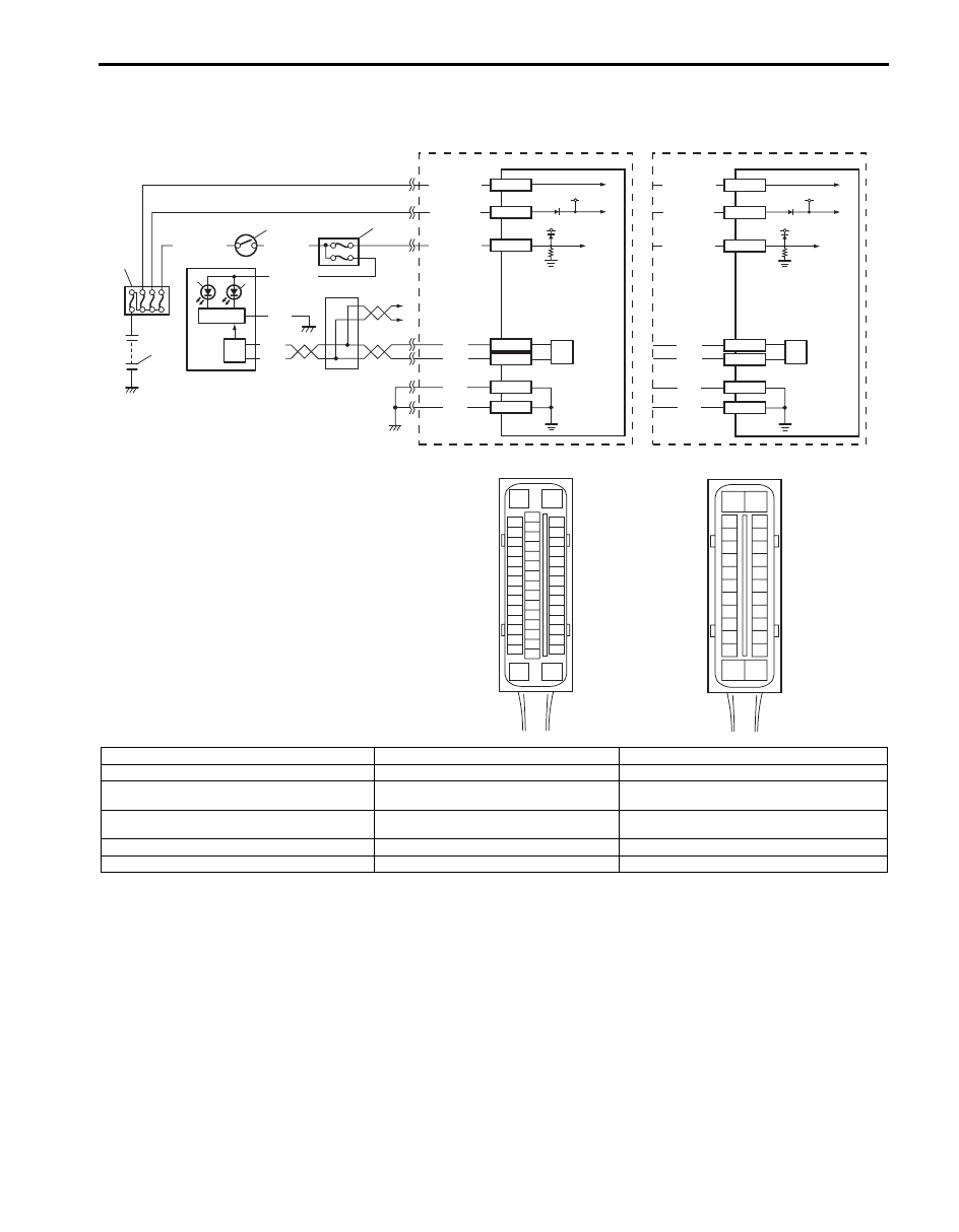
ABS Warning Lamp Does Not Come ON at Ignition Switch ON
S5JB0B4504008
Wiring Diagram
Circuit Description
Operation (ON/OFF) of ABS warning lamp is controlled by ABS (ESP
®) control module through lamp driver module in
combination meter.
If the antilock brake system is in good condition, ABS (ESP
®) control module turns ABS warning lamp ON at the
ignition switch ON, keeps it ON for 2 seconds and then turns it OFF. If an abnormality in the system is detected, ABS
warning lamp is turned ON continuously by ABS (ESP
®) control module. Also, it is turned ON continuously by lamp
driver module when the connector of ABS (ESP
®) control module is disconnected.
3
4
2
1
[C]
E53-16
E53-47
12V
12V
E53-32
E53-1
E53-35
GRN/ORN
PPL/RED
BLK/YEL
WHT/GRN
WHT/RED
WHT/BLU
BLK
BLK
BLK
RED
WHT
RED
WHT
E53-13
E53-44
11
10
5
7
8
6
9
E53
16
1
15
2
3
4
5
6
7
8
9
10
11
12
13
14
17
18
19
20
21
22
23
24
25
26
27
28
29
30
31
32
33
34
35
36
37
38
39
40
41
42
43
44
45
46
47
E03-13
E03-26
12V
12V
E03-1
E03-14
E03-7
GRN/ORN
WHT/RED
WHT/BLU
BLK
BLK
RED
WHT
E03-12
E03-6
13
9
[D]
E03
15
16
17
18
19
20
21
22
23
24
25
2
3
4
5
6
7
8
9
10
11
12
1
13
14
26
9
12
[A]
[B]
I6JB01450005-01
[A]: With ESP
®
3. Ignition switch
9. CAN driver
[B]: Without ESP
®
4. Junction block assembly
10. Junction connector
[C]: ESP
® control module connector (viewed from
terminal side)
5. Combination meter
11. To BCM, 4WD control module, immobilizer
control module (ICM) and steering angle sensor
[D]: ABS control module connector (viewed from
terminal side)
6. ABS warning lamp
12. ESP
® hydraulic unit / control module assembly
1. Battery
7. EBD warning lamp (Brake warning lamp)
13. ABS hydraulic unit / control module assembly
2. Main fuse box
8. Lamp driver module