Suzuki Grand Vitara JB419. Service manual - part 77
 

  Index      Suzuki     Suzuki Grand Vitara JB419 (with F9Q engine) - service and repair manual 2007 year


Search            


Content   ..  75  76  77  78   ..


Suzuki Grand Vitara JB419. Service manual - part 77


Transfer: 3C-6

NOTE
“O” in transfer position indicator column of the above table means indicator lights up when DTC is 
detected.


Scan Tool Data

S5JB0B3304009

)

 C1243

Internal circuit malfunction of 
4WD control module

EEPROM error

{

)

 C1246

Clutch pedal position (CPP) 
switch circuit short

CPP switch signal is input when vehicle speed is 
30 km/h (19 mph).

{

)

 U1073

Control module communication 
bus off

Transmitting and receiving error of 4WD control 
module for specified time continuously.

{

)

 U1100

Lost communication with ECM

Receiving error of 4WD control module from 
ECM for specified time continuously.

{

)

 U1121

Lost communication with ABS / 
ESP

® control module

Receiving error of 4WD control module from 
ABS / ESP

® control module for specified time 

continuously.

{

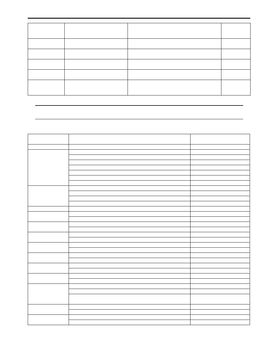
Scan Tool Data

Vehicle Condition

Normal Condition / 

Reference Value

Vehicle speed

At vehicle stop

0 km/h, 0 mph

Actuator Pos Sen

Transfer shifted to 4H position

4H

Transfer being shifted between 4H-lock and 4H position

4H-lock – 4H

Transfer shifted to 4H-lock position

4H-lock

Transfer being shifted between 4H and N position

4H – N

Transfer shifted to 4L-lock position

4L-lock

Transfer being shifted between N and 4L-lock position

N – 4L-lock

Transfer shifted to N position

N

Actuator motor Pos

Transfer shifted to 4H position

4H

Transfer shifted to 4H-lock position

4H-lock

Transfer shifted to 4L-lock position

4L-lock

Transfer shifted to N position

N

Battery voltage

Ignition switch ON and engine stop

10 – 14 V

4L/N switch

Transfer shifted to 4L-lock or N position

ON

Transfer shifted to 4H or 4H-lock position

OFF

Center diff lock SW

Transfer shifted to 4H or N position

ON

Transfer shifted to 4H-lock or 4L-lock position

OFF

N range signal (AT)

A/T shifted to “N” range

ON

A/T shifted to other than “N” range

OFF

CPP switch (MT)

Clutch pedal depressed

OFF

Clutch pedal released

ON

Mode switch 1

Transfer switch selected to N position

ON

Transfer switch selected to 4H, 4H-lock or 4L-lock position

OFF

Mode switch 2

Transfer switch selected to 4H, 4H-lock or N position

ON

Transfer switch selected to 4L-lock position

OFF

Mode switch 3

Transfer switch selected to 4H-lock or 4L-lock position

ON

Transfer switch selected to 4H or N position

OFF

Warning buzzer

Buzzer not being sound

OFF

Transfer shifted to N Position

N Pos

Transfer shifted to disagreement of transfer switch and transfer 
position

Error

ABS active

ABS operating

ON

ABS not operating

OFF

ESP

® active

ESP

® operating

ON

ESP

® not operating

OFF

DTC No.

Detecting item

Detecting condition

(DTC will set when detecting)

Transfer 
position 

indicators

3C-7 Transfer: 

Scan Tool Data Definitions

S5JB0B3304010

Vehicle Speed (KM/H, MPH):  

This parameter indicates vehicle speed calculated by 4WD control module.

Actuator Pos Sen (Transfer shift actuator motor position switch) (4H / 4H-lock / 4L-lock / N / 4H-lock-4H / 4H-N 

/ N-4L-lock):  
This parameter indicates transfer shift actuator motor position switch status detected by 4WD control module.

Actuator motor Pos (Transfer shift actuator motor position) (4H / 4H-lock / 4L-lock / N):  

This parameter indicates transfer shift actuator motor position detected by 4WD control module using transfer shift 
actuator motor position.

Battery voltage (V):  

This parameter indicates battery voltage detected by 4WD control module.

4L / N switch (ON / OFF):  

This parameter indicates 4L / N switch status detected by 4WD control module.

Center diff lock Sw (ON / OFF):  

This parameter indicates center differential lock switch status detected by 4WD control module.

N range signal (AT) (ON / OFF):  

This parameter indicates A/T shift position (“N” range or not) detected by 4WD control module.

CPP switch (Clutch pedal position switch) (MT) (ON / OFF):  

This parameter indicates clutch pedal position switch status detected by 4WD control module using CPP switch.

Mode switch 1 (Transfer switch) (ON / OFF):  

ON: Transfer switch to N position.
OFF: Transfer switch to other than N position.

Mode switch 2 (Transfer switch) (ON / OFF):  

ON: Transfer switch to other than 4L-lock position.
OFF: Transfer switch to 4L-lock position.

Mode switch 3 (Transfer switch) (ON / OFF):  

ON: Transfer switch to 4H-lock or 4L-lock position.
OFF: Transfer switch to 4H or N position.

Warning buzzer (OFF / N Pos / Error):  

This parameter indicates if buzzer is being commanded by 4WD control module.

ABS active (ON / OFF):  

This parameter indicates ABS status detected by 4WD control module.

ESP

® active (ON / OFF):  

This parameter indicates ESP

® status detected by 4WD control module.

Transfer: 3C-8

4WD Control Symptom Diagnosis

S5JB0B3304011

Diagnose transfer assembly after performing the following inspections.

1) Perform 4WD control system check referring to “4WD Control System Check in related manual”.
2) Confirm 4WD control system operation referring to “4WD Control System Operation in related manual”

Condition

Possible cause

Correction / Reference Item

Transfer does not operate 
(Transfer position 
indicator does not 
operate)

Transfer switch faulty

Check switch referring to “Transfer Switch 
Inspection in related manual”.

Transfer shift actuator faulty

Check transfer shift actuator referring to 
“Transfer Assembly Inspection in related 
manual”.

4L/N switch and/or switch center 
differential lock switch faulty

Check switch referring to “Transfer Assembly 
Inspection in related manual”.

CPP switch faulty (for M/T model)

Check CPP switch referring to “Clutch Pedal 
Position (CPP) Switch Inspection and 
Adjustment in Section 5C in related manual”.

Wiring or grounding faulty

Repair as necessary.

4WD control module faulty

Check 4WD control module referring to 
“Inspection of 4WD Control Module and Its 
Circuits in related manual”.

Transfer refuses to 
operate (Transfer position 
indicator flashes, and 
then transfer does not 
shift)

Transfer shift actuator faulty

Check transfer shift actuator referring to 
“Transfer Assembly Inspection in related 
manual”.

4L/N switch and/or center differential 
lock switch faulty

Check switch referring to “Transfer Assembly 
Inspection in related manual”.

Distorted control cover shift shaft or shift 
fork

Check shift fork referring to “Transfer Assembly 
Inspection in related manual”.

Weakened control cover shift shaft 
spring

Check spring referring to “Transfer Assembly 
Inspection in related manual”.

Distorted or dispositioned control cover 
shift shaft snap ring and washer

Check snap ring and washer referring to 
“Transfer Assembly Inspection in related 
manual”.

Worn chamfered tooth on sleeve or gear Check chamfered tooth and gear referring to 

“Transfer Assembly Inspection in related 
manual”.

Wiring or grounding faulty

Repair as necessary.

4WD control module faulty

Check 4WD control module referring to 
“Inspection of 4WD Control Module and Its 
Circuits in related manual”.

Gear slipping out of mesh Worn control cover shift shaft

Check control cover shift shaft referring to 
“Transfer Assembly Inspection in related 
manual”.

Worn shift fork or sleeve

Check shift fork or sleeve referring to “Transfer 
Assembly Inspection in related manual”.

Weak or damaged control cover shift 
shaft spring

Check spring referring to “Transfer Assembly 
Inspection in related manual”.

Worn bearings on input gear or counter 
gear

Check bearing referring to “Transfer Assembly 
Inspection in related manual”.

Worn chamfered tooth on sleeve or gear Check sleeve and gear referring to “Transfer 

Assembly Inspection in related manual”.

Missing or disengagement of circlip(s)

Check circlip(s) referring to “Transfer Assembly 
Inspection in related manual”.

Noise

Damaged or worn bearing(s)

Refer to “Transfer Assembly Inspection in 
related manual”.

Damaged or worn gear(s)

Refer to “Transfer Assembly Inspection in 
related manual”.

Damaged or worn chamfered tooth on 
sleeve or gear

Refer to “Transfer Assembly Inspection in 
related manual”.

3C-9 Transfer: 

DTC U1073: Control Module Communication Buss Off

S5JB0B3304026

Wiring Diagram

WHT

RED

WHT

RED

G44-18

G44-19

G44

[A]

[B]

[C]

[G]

1

2

3

4

5

6

7

8

9

10

11

14

15

16
36

34 33 32 31 30 29

24 23

37

18

19

20

G28-8

G28-10

WHT/BLU

WHT/BLU

WHT/RED

WHT/RED

E23-4
E23-19

WHT

RED

E03-12

E03-10

E03-6

E03-8

WHT

RED

E92-17

E92-7

WHT

RED

E91-22
E91-23

WHT

RED

G31-1
G31-3

6

5

16 15 14 13 12 11

4 3

24 23

21

22

10 9

8

7

2

1

19

20

18 17

E92

17 16

26 25

15 14

6

5

3

4

2

13 12

23 22

24

11 10 9

21 20 19

8 7

18

1

E93

2 1

E23

C37

3

4

18

19

5

6

7

10

11

17

20

47 46

49

50

51

21

22

52

16

25

9

24

14
29

55

57

5453

59

60

58

2

26

27

28

15

30

56

48

32 31

34

35

36

37

40

42

3938

44

45

43

41

33

1

12

13

23

8

3

4

18

19

5

6

7

10

11

17

20

47 46

49

50

51

21

22

52

16

25

9

24

14

29

55

57

5453

59

60

58

26

27

28

15
30

56

48

32 31

34

35

36

37

40

42

3938

44

45

43

41

33

12

13

23

8

1

2

3

4

5

6

7

8

9

10

11

17

1615141312

2221201918

G28

[E]

G31

1

2

3

4

7

8

9

10

11

14

15

16
36

34

35

24 23

21

22

28 27

25

26

37

39 38

40

18 17

13 12

19

20

[D]

E03

15
16
17
18
19
20
21
22
23
24
25

2
3
4
5
6
7
8
9

10
11
12

1

13

14

26

1

2

3

4

5

6

7

8

9

10

11

12

13

14

15

16

17

18

19

20

21

22

23

24

25

26

[F]

E91

WHT

RED

G31-2
G31-4

[H]

8

7

6

5

4

3

2

1

9

10

11

12

13

14

15

16

1

2

3

4

8

5

6

7

[I]

E53

16

1

15

2

3

4

5

6

7

8

9

10

11

12

13

14

17

18

19

20

21

22

23

24

25

26

27

28

29

30

31

32

33

34

35

36

37

38

39

40

41

42

43

44

45

46

47

9

E53-13

E53-42

E53-44

E53-46

I6JB01331002-02

[A]: Keyless start control module connector (if equipped) (viewed from harness side)

1. BCM

[B]: ECM connector (viewed from harness side)

2. 4WD control module

[C]: TCM connector (for A/T model) (viewed from harness side)

3. TCM (if equipped)


Content   ..  75  76  77  78   ..