Suzuki Grand Vitara JB419. Service manual - part 44
 

  Index      Suzuki     Suzuki Grand Vitara JB419 (with F9Q engine) - service and repair manual 2007 year


Search            


Content   ..  42  43  44  45   ..


Suzuki Grand Vitara JB419. Service manual - part 44


Engine Mechanical:  1D-22

21) Before lowering engine with transmission and front 

suspension frame from engine compartment, 
recheck to make sure all hoses, electric wires and 
cables are disconnected.

22) Lower engine with transmission and front 

suspension frame from engine compartment.

CAUTION

!


Before lowering engine, in order to avoid 
damage to A/C compressor, make clearance 
by rising them.


23) Disconnect transmission from engine referring to 

“Manual Transmission Assembly Dismounting and 
Remounting in Section 5B”,
 if necessary.

Installation

CAUTION

!


Before starting engine (including when performing oil level check and air bleeding process of cooling 
system) for the first time after installing turbocharger, be sure to lubricate turbocharger, referring to 
“CAUTION” in “Installation” under “Turbocharger Assembly Removal and Installation”. Otherwise, 
lack of lubrication will cause turbocharger damage.


1) Connect transmission to engine referring to “Manual Transmission Assembly Dismounting and Remounting in 

Section 5B”, if removed.

2) Lift engine with transmission and front suspension frame to engine compartment using engine jack.

CAUTION

!


Before lifting engine, in order to avoid damage to A/C compressor, make clearance by rising them.


3) Tighten engine rear mounting member bolt referring to “Engine Mounting Components”.
4) Carry out Step 5) through 19) of “Installation” under “Front Suspension Frame, Stabilizer Bar and/or Bushings 

Removal and Installation in Section 2B in related manual” in order to install engine with front suspension frame.

5) Remove engine jack.
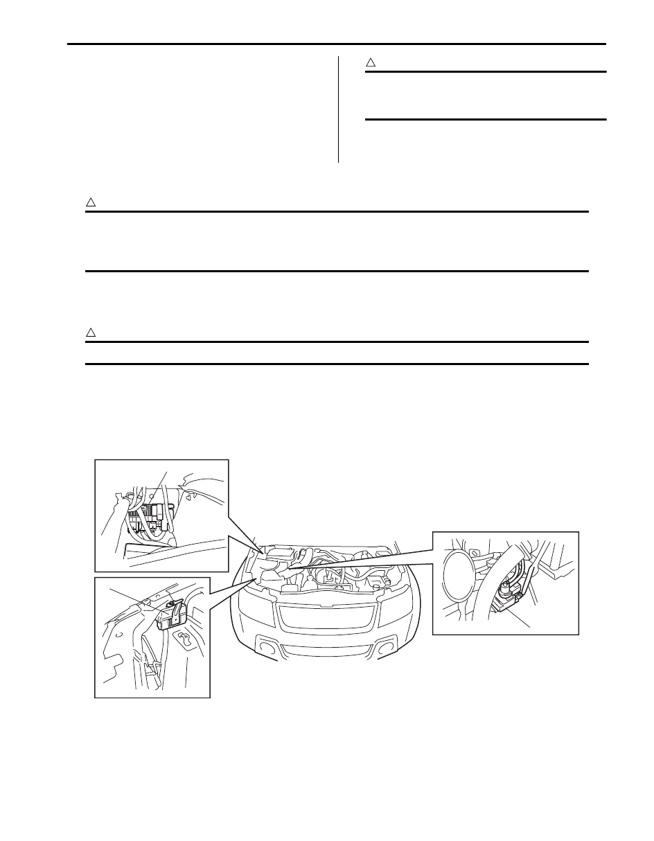
6) Install relay box (1), fuse box No.1 (2) and boost pressure control solenoid valve (3) to vehicle body.

1

2

3

I5JB0B140044-01

1D-23 Engine Mechanical: 

7) Connect connectors and wire harness disconnected 

in removal procedure.

8) Connect hoses disconnected in removal procedure.
9) Install intercooler inlet pipe (1).

Tightening torque
Intercooler inlet hose clamp (a):  4.5 N·m (0.45 
kgf-m, 3.5 lb-ft)

10) Install air cleaner case (1) and turbocharger inlet 

hose (2), and connect MAF sensor connector (3).

Tightening torque
Inlet hose clamp (a):  2.5 N·m (0.25 kgf-m, 2.0 lb-
ft)

11) Connect P/S suction hose and low pressure return 

hose referring to “P/S Hose / Pipe Components in 
Section 6C”.

12) Install A/C compressor to its bracket referring to 

“Compressor Assembly Removal and Installation in 
Section 7B”
, if removed.

13) Install front and rear propeller shafts referring to 

“Propeller Shaft Removal and Installation in Section 
3D”.

14) Install exhaust No.1 pipe referring to “Exhaust 

System Components in Section 1K”.

15) Install shift control lever referring to “Transmission 

Shift Control Lever Removal and Installation in 
Section 5B”
.

16) Install accessory drive belt referring to “Accessory 

Drive Belt and Idler Pulley Removal and Installation 
in Section 1J”.

17) Check all removed parts are back in place.
18) Refill coolant referring to “Cooling System Refilling in 

Section 1F”.

19) Refill engine oil referring to “Engine Oil and Filter 

Change in Section 0B”.

20) After installation, bleed air from clutch system 

referring to “Air Bleeding of Brake System in Section 
4A in related manual” for air bleeding procedure.

21) Install battery, and connect positive (+) and negative 

(–) cable at battery.

22) Bleed air in fuel system referring to “Air Bleeding of 

Fuel System in Section 1G”.

23) Start engine, and check coolant, oil and exhaust gas 

leakage at each connection.

24) Check fuel leakage referring to “Fuel Leakage Check 

Procedure in Section 1G”.

25) Check DTC referring to “DTC Check in Section 1A”.

(a)

1

I5JB0B140045-02

1

3

2

(a)

(a)

I5JB0B140046-02

Engine Mechanical:  1D-24

EGR Valve Components

S5JB0B1406054

2

1

2

(b)

(c)

(c)

2

4

3-1

(d)

(e)

6-1

6-2

3-2

(a)

(c)

5

I5JB0B140047-06

1. EGR valve 

5. EGR cooler 

: 25 N

⋅m (2.5 kgf-m, 18.0 lb-ft)

2. Gasket

6-1. EGR pipe stiffener bolt (with washer)

: 11 N

⋅m (1.1 kgf-m, 8.0 lb-ft)

3-1. Clamp (type A)

6-2. EGR pipe stiffener bolt (without washer)

: 9 N

⋅m (0.9 kgf-m, 7.0 lb-ft)

3-2. Clamp (type B)

: 5 N

⋅m (0.5 kgf-m, 4.0 lb-ft)

: Do not reuse.

4. EGR pipe 

: 18 N

⋅m (1.8 kgf-m, 13.0 lb-ft)

1D-25 Engine Mechanical: 

EGR Valve Removal and Installation

S5JB0B1406071

CAUTION

!


When replacing EGR valve, perform 
“Initialize EGR valve data” mode of SUZUKI 
scan tool referring to “EGR Valve Data 
Initialization”.


Removal

1) Disconnect negative (–) cable at battery.
2) Remove engine cover.
3) Remove air intake pipe referring to “Air intake Pipe 

Removal and Installation”.

4) Disconnect EGR valve connector (1) and EGR pipe 

(2) from EGR valve (3).

5) Remove EGR valve from intake manifold.

Installation

1) Install EGR valve (1) to intake manifold.

Tightening torque
EGR valve bolt (a):  25 N·m (2.5 kgf-m, 18.0 lb-ft)

2) Connect EGR valve connector (2) and EGR pipe (3) 

to EGR valve.

3) Install air intake pipe referring to “Air intake Pipe 

Removal and Installation”.

4) Install engine cover.
5) Connect negative (–) cable at battery.

2

3

1

3

I5JB0B120007-01

3

1

2

1

(a)

I5JB0B120008-01


Content   ..  42  43  44  45   ..