Suzuki Grand Vitara JB419. Service manual - part 9
 

  Index      Suzuki     Suzuki Grand Vitara JB419 (with F9Q engine) - service and repair manual 2007 year


Search            


Content   ..  7  8  9  10   ..


Suzuki Grand Vitara JB419. Service manual - part 9


Engine General Information and Diagnosis:  1A-13

Diagnostic Information and Procedures

Malfunction Indicator Lamp (MIL) Check

S5JB0B1104001

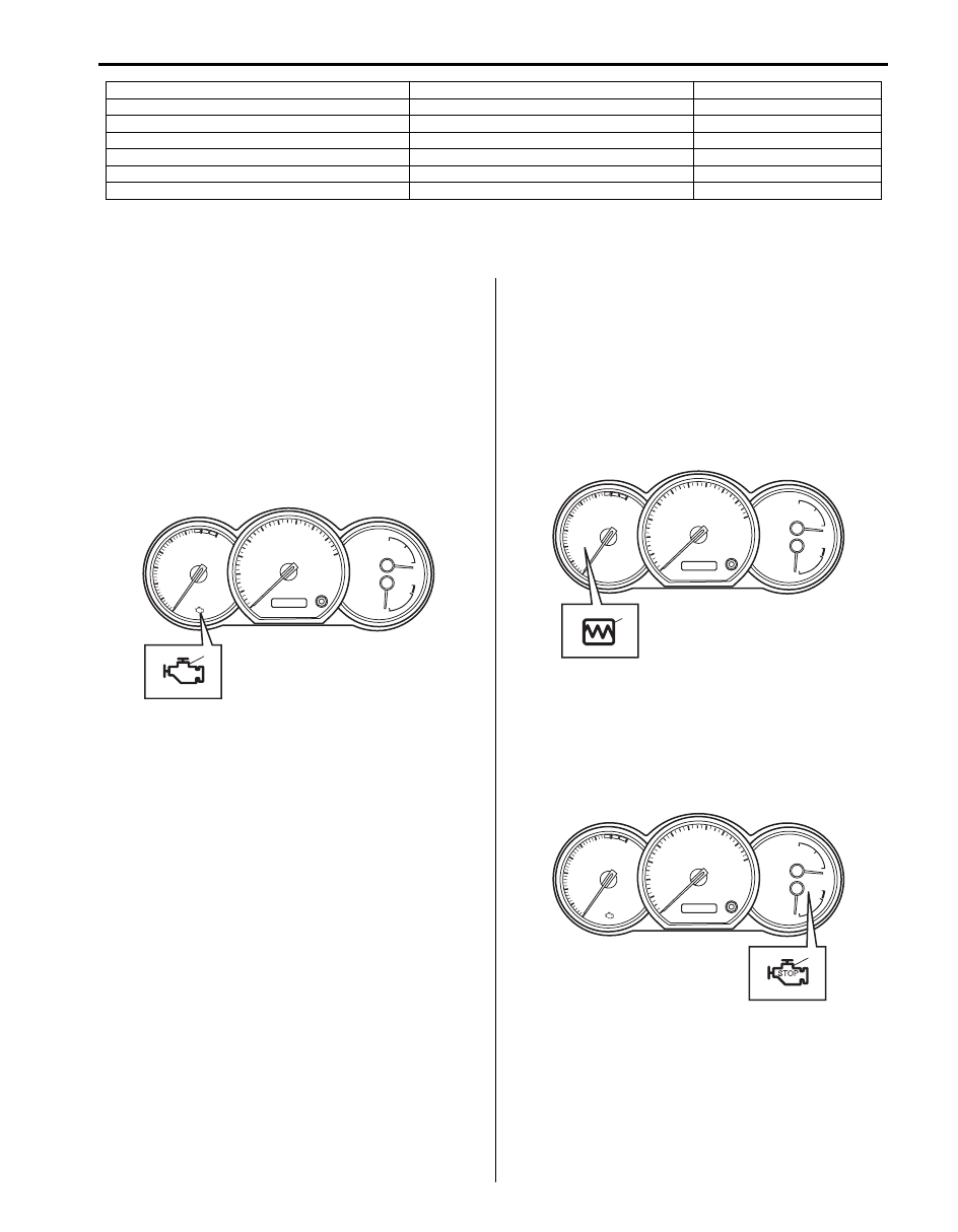
Malfunction indicator lamp (1) signals an antipollution 
system failure. 
Check that it lights up for 3 seconds after the ignition 
switch is turned ON, and then it goes OFF (automatic 
test procedure). 
If light remains ON after an automatic test procedure, go 
to “DTC Check”.
After the ignition switch is turned ON, if light does not 
light up or remains ON, check that malfunction indicator 
lamp circuit.

Injection Warning Light (Gravity 1 Fault) Check 

S5JB0B1104002

Injection warning light (1) serves to indicate proper 
functioning and to signal system failures.
After the ignition switch is turned ON, if lights remains 
ON, go to “DTC Check”.
If injection warning light flashes ON and OFF, there is 
some trouble in the immobilizer control system referring 
to “On-Board Diagnostic System Description (Self-
diagnosis Function) in Section 10C”.

Red Stop Warning Light (Gravity 2 Fault) Check

S5JB0B1104003

Red stop warning light (1) serves to indicate proper 
functioning and to signal system failures. 
After the ignition switch is turned ON. if light remains ON, 
go to “DTC Check”.

t: Inlet throttle valve

u: EGR valve 

v: Boost pressure control solenoid valve

w: Additional heater relay No.1

x: Additional heater relay No.2
y: Additional heater relay No.3

Information sensors

Control devices

Others

1

I5JB0B110011-02

1

I5JB0B110012-02

1

I5JB0B110013-02

1A-14 Engine General Information and Diagnosis: 

Engine and Emission Control System Check

S5JB0B1104004

Refer to the following items for the details of each step.

Step 1: Customer Complaint Analysis
Record details of the problem (failure, complaint) and how it occurred as described by the customer. For this purpose, 
use of such an inspection form will facilitate collecting information to the point required for proper analysis and 
diagnosis.

Step

Action

Yes

No

1

)

 Customer complaint analysis

1) Perform customer complaint analysis referring to “Step 

1: Customer Complaint Analysis: ”.

Was customer complaint analysis performed?

Go to Step 2.

Perform customer 
complaint analysis.

2

)

 Visual inspection

1) Perform visual inspection referring to “Step 2: Visual 

Inspection: ”.

Is there any faulty condition?

Repair or replace 
malfunction part, and go 
to Step 3.

Go to Step 3.

3

)

 DTC check, record and clearance

1) Check for DTC referring to “Step 3: DTC Check, Record 

and Clearance: ”.

Is there any DTC(s)?

Record and clear DTC 
referring to “DTC 
Clearance” an
d go to 
Step 5.

Go to Step 4.

4

)

 Engine basic inspection and fault finding – customer 

complaints
1) Check and repair according to “Step 4: Engine Basic 

Inspection and Fault Finding-Customer Complaints: ”.

Is there any faulty condition?

Repair or replace 
malfunction part and 
then go to Step 8.

Go to Step 8.

5

)

 Recheck DTC

1) Recheck DTC referring to “Step 5: Recheck DTC: ”.

Is there any DTC(s)?

Go to Step 6.

Go to Step 7.

6

)

 Troubleshooting for DTC

1) Check and repair according to applicable DTC diag. flow 

referring to “Step 6: Troubleshooting for DTC (See each 
DTC Diag. Flow): ”.

Is there any faulty condition?

Repair or replace 
malfunction part and 
then go to Step 8.

Go to Step 7.

7

)

 Intermittent problems check

1) Check for intermittent problems referring to “Step 7: 

Intermittent Problems Check: ”.

Is there any faulty condition?

Repair or replace 
malfunction part(s), and 
go to Step 8.

Go to Step 8.

8

)

 Final confirmation test

1) Clear DTC if any.
2) Perform final confirmation test referring to “Step 8: Final 

Confirmation Test: ”.

Is there any problem symptom, DTC or abnormal condition?

Go to Step 5.

End.

Engine General Information and Diagnosis:  1A-15

Customer problem inspection form (Example)

NOTE
The form is a standard sample. It should be modified according to conditions characteristic of each 
market.


I2RH01110010-02

1A-16 Engine General Information and Diagnosis: 

Step 2: Visual Inspection
As a preliminary step, be sure to perform visual check of 
the items that support proper function of the engine 
referring to “Visual Inspection”.

Step 3: DTC Check, Record and Clearance
First, check DTC, referring to “DTC Check”. If DTC is 
indicated, record and clear DTC by referring to “DTC 
Clearance”. 
Attempt to diagnose a trouble based on DTC in this step 
only or failure to clear the DTC in this step will lead to 
incorrect diagnosis, trouble diagnosis of a normal circuit 
or difficulty in troubleshooting.

Step 4: Engine Basic Inspection and Fault Finding-
Customer Complaints
Perform basic engine check according to “Engine Basic 
Inspection”
 first. When the end of the flow table has been 
reached, check the parts of the system suspected as a 
possible cause referring to “Fault Finding-Customer 
Complaints” an
d based on symptoms appearing on the 
vehicle (symptoms obtained through steps of customer 
complaint analysis, trouble symptom confirmation and/or 
basic engine check) and repair or replace faulty parts, if 
any.

Step 5: Recheck DTC
Refer to “DTC Check” for checking procedure.

Step 6: Troubleshooting for DTC (See each DTC 
Diag. Flow)
Based on the DTC indicated in Step 5 and referring to 
the applicable DTC diag. flow, locate the cause of the 
trouble, namely in a sensor, switch, wire harness, 
connector, actuator, ECM or other part and repair or 
replace faulty parts.

Step 7: Intermittent Problems Check
Check parts where an intermittent trouble is easy to 
occur (e.g., wire harness, connector, etc.), referring to 
“Intermittent and Poor Connection Inspection in Section 
00 in related manual” and related circuit of DTC 
recorded in Step 2.

Step 8: Final Confirmation Test
Confirm that the problem symptom has gone and the 
engine is free from any abnormal conditions. If what has 
been repaired is related to the DTC, clear the DTC once 
and then recheck DTC and confirm that no DTC is 
indicated.

DTC Check

S5JB0B1104005

1) Prepare SUZUKI scan tool or OBD generic scan 

tool.

2) Connect it to data link connector (DLC) (1) located 

on underside of instrument panel at driver’s seat 
side.

Special tool
(A):  SUZUKI scan tool

3) Turn ignition switch ON.
4) Read DTC, according to instructions displayed on 

scan tool and print them or write them down. Refer to 
scan tool operator’s manual for further details.
If communication between scan tool and ECM is not 
possible, check if scan tool is communicable by 
connecting it to ECM in another vehicle.
If communication is possible in this case, scan tool is 
in good condition. Then check data link connector 
and serial data line (circuit) in the vehicle with which 
communication was not possible.

5) After completing the check, turn ignition switch OFF 

and disconnect scan tool from data link connector.

DTC Clearance

S5JB0B1104006

NOTE
In case that DTC P0606 D6 can not be cleared 
according to this procedure, clear DTC by 
specified procedure described in “DTC 
P0606: ECM / PCM Processor Malfunction”.


1) Connect SUZUKI scan tool to data link connector in 

the same manner as when making this connection 
for DTC check.

2) Turn ignition switch OFF and then ON (but engine at 

stop).

3) Erase DTC according to instructions displayed on 

scan tool. Refer to scan tool operator’s manual for 
further details.

4) After completing the clearance, turn ignition switch 

OFF and disconnect scan tool from data link 
connector.

(A)

1

I5JB0A110019-01


Content   ..  7  8  9  10   ..