Suzuki Grand Vitara JB416 / JB420 (ESP model). Service manual - part 83
5A-31 Automatic Transmission/Transaxle:
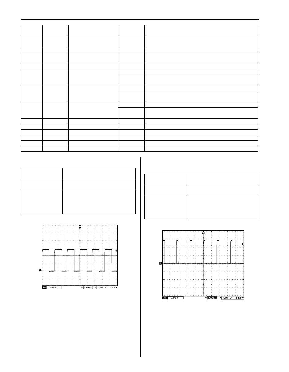
Reference Waveform No. 1
Pressure control solenoid valve signal at engine idling.
Reference Waveform No. 2
TCC pressure control solenoid valve signal at engine
idling.
14
ORN
Output shaft speed
sensor (–)
2 – 3 V
Ignition switch ON, engine at stop
15
—
—
—
—
16
PNK
Input shaft speed
sensor (–)
2 – 3 V
Ignition switch ON, engine at stop
17
—
—
—
—
18
GRN/WHT
Transmission range
sensor (“L” range)
8 – 14 V
Ignition switch ON, selector lever at “L” range
0 – 1 V
Ignition switch ON, selector lever at other than “L”
range
19
GRN/ORN
Transmission range
sensor (“2” range)
8 – 14 V
Ignition switch ON, selector lever at “2” range
0 – 1 V
Ignition switch ON, selector lever at other than “2”
range
20
PNK
Transmission range
sensor (“P” range)
8 – 14 V
Ignition switch ON, selector lever at “P” range
0 – 1 V
Ignition switch ON, selector lever at other than “P”
range
21
—
—
—
—
22
—
—
—
—
23
PPL/WHT Data link connector
8 – 14 V
Ignition switch ON
24
—
—
—
—
25
—
—
—
—
26
—
—
—
—
Terminal Wire color
Circuit
Standard
voltage
Condition
Measurement
terminal
CH1: “E92-4” to “E92-1”
Oscilloscope
setting
CH1: 5 V/DIV
TIME: 20 ms/DIV
Measurement
condition
• After warmed up to normal
operating temperature
• Engine at specified idle speed
with “P” range.
I3RM0B510029-01
Measurement
terminal
CH1: “E92-5” to “E92-1”
Oscilloscope
setting
CH1: 5 V/DIV
Time: 2 ms/DIV
Measurement
condition
• After warmed up to normal
operating temperature
• Engine at specified idle speed
with “P” range
I4RS0A510024-01