Suzuki Grand Vitara JB416 / JB420 (ESP model). Service manual - part 52
4E-2 ABS:
General Description
ABS Description
S5JB0E4501001
ABS is controlled by ABS control module or by ESP
®
control module (if equipped).
ABS activation and control with ESP
® are done by
ESP
® hydraulic unit / control module assembly.
Regarding TCS and stability control excluding ABS
system with ESP
®, refer to Section 4F.
The ABS (Antilock Brake System) controls the fluid
pressure applied to the wheel cylinder of each brake
from the master cylinder so that each wheel is not locked
even when hard braking is applied.
This ABS has also the following function.
While braking is applied, but before ABS control
becomes effective, braking force is distributed between
the front and rear so as to prevent the rear wheels from
being locked too early for better stability of the vehicle.
The main component parts of this ABS include the
following parts in addition to those of the conventional
brake system.
• Wheel speed sensor which senses revolution speed
of each wheel and outputs its signal.
• ABS warning lamp which lights to inform abnormality
when system fails to operate properly.
• ABS (ESP
®) hydraulic unit / control module assembly
is incorporated ABS (ESP
®) control module, ABS
(ESP
®) hydraulic unit (actuator assembly), solenoid
valve power supply driver (transistor), solenoid valve
driver (transistor), pump motor driver (transistor).
– ABS (ESP
®) control module which sends operation
signal to ABS (ESP
®) hydraulic unit to control fluid
pressure applied to each wheel cylinder based on
signal from each wheel speed sensor so as to
prevent wheel from locking.
– ABS (ESP
®) hydraulic unit which operates
according to signal from ABS (ESP
®) control
module to control fluid pressure applied to wheel
cylinder of each 4 wheels.
– Solenoid valve power supply driver (transistor)
which supplies power to solenoid valve in ABS
(ESP
®) hydraulic unit.
– Solenoid valve driver (transistor) which controls
each solenoid valves in ABS (ESP
®) hydraulic unit.
– Pump motor driver (transistor) which supplies
power to pump motor in ABS (ESP
®) hydraulic
unit.
This ABS is equipped with Electronic Brake force
Distribution (EBD) system that controls a fluid pressure
of rear wheels to best condition, which is the same
function as that of proportioning valve, by the signal from
wheel sensor independently of change of load due to
load capacity and so on. And if the EBD system fails to
operate properly, the brake warning lamp lights to inform
abnormality.
Self-Diagnosis Description
S5JB0E4501004
ABS (ESP
®) control module diagnoses conditions of the
system component parts (whether or not there is any
abnormality) all the time and indicates the results
(warning of abnormality occurrence and DTC) through
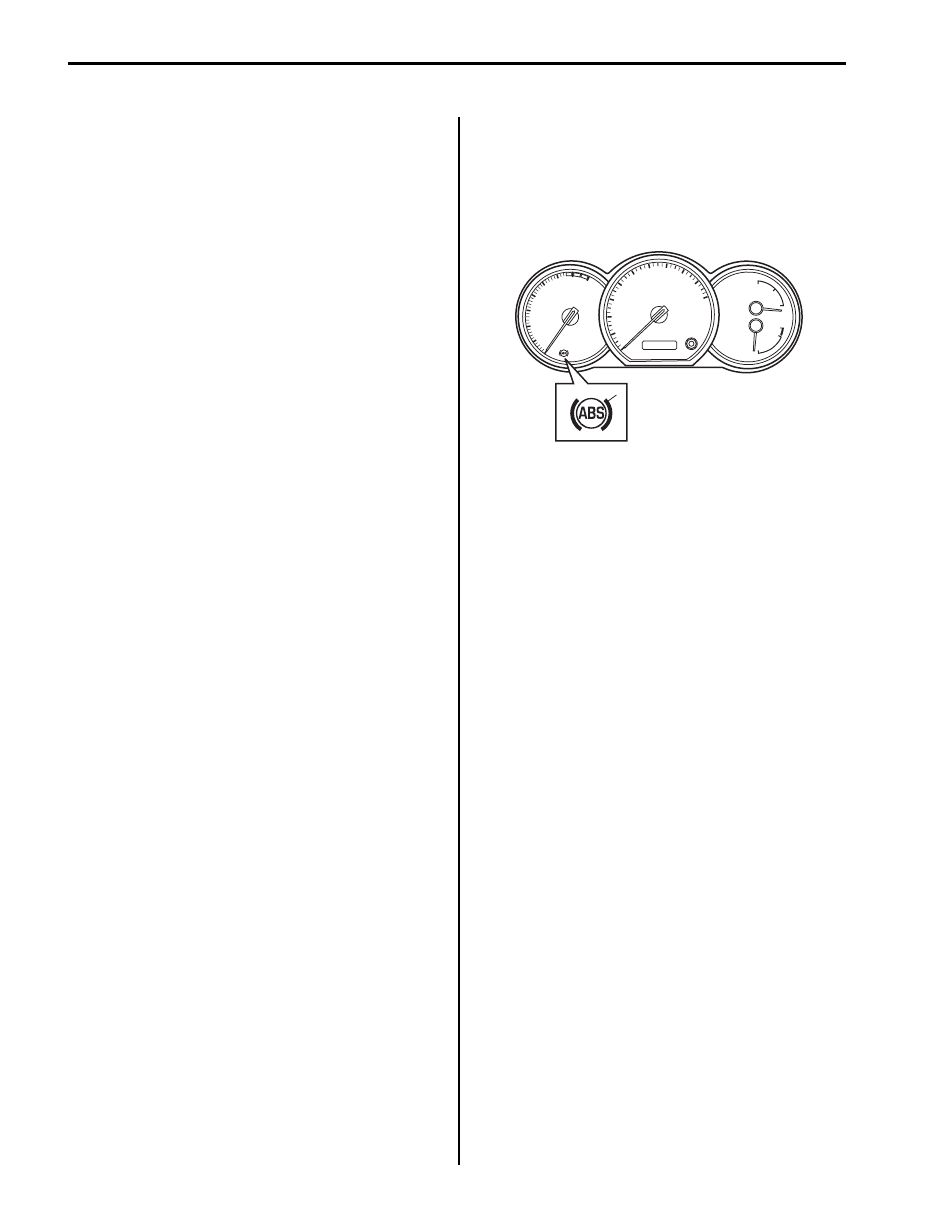
the ABS warning lamp (1) as described.
• When ignition switch is turned ON, ABS warning lamp
lights for 2 seconds to check its circuit.
• When no abnormality has been detected (the system
is in good condition), ABS warning lamp turns OFF
after 2 seconds.
• When an abnormality in the system is detected, ABS
warning lamp lights and the area where that
abnormality lies is stored in the memory of EEPROM
in ABS (ESP
®) control module.
1
I5JB0A450001-01