Suzuki Grand Vitara JB416 / JB420 (ESP model). Service manual - part 13
1A-48 Engine General Information and Diagnosis:
Inspection of ECM and Its Circuits
S5JB0E1104080
ECM and its circuits can be checked by measuring voltage, pulse signal and resistance with special tool connected.
CAUTION
!
ECM cannot be checked by itself. It is strictly prohibited to connect voltmeter or ohmmeter to ECM
with ECM connectors disconnected from it.
Voltage Check
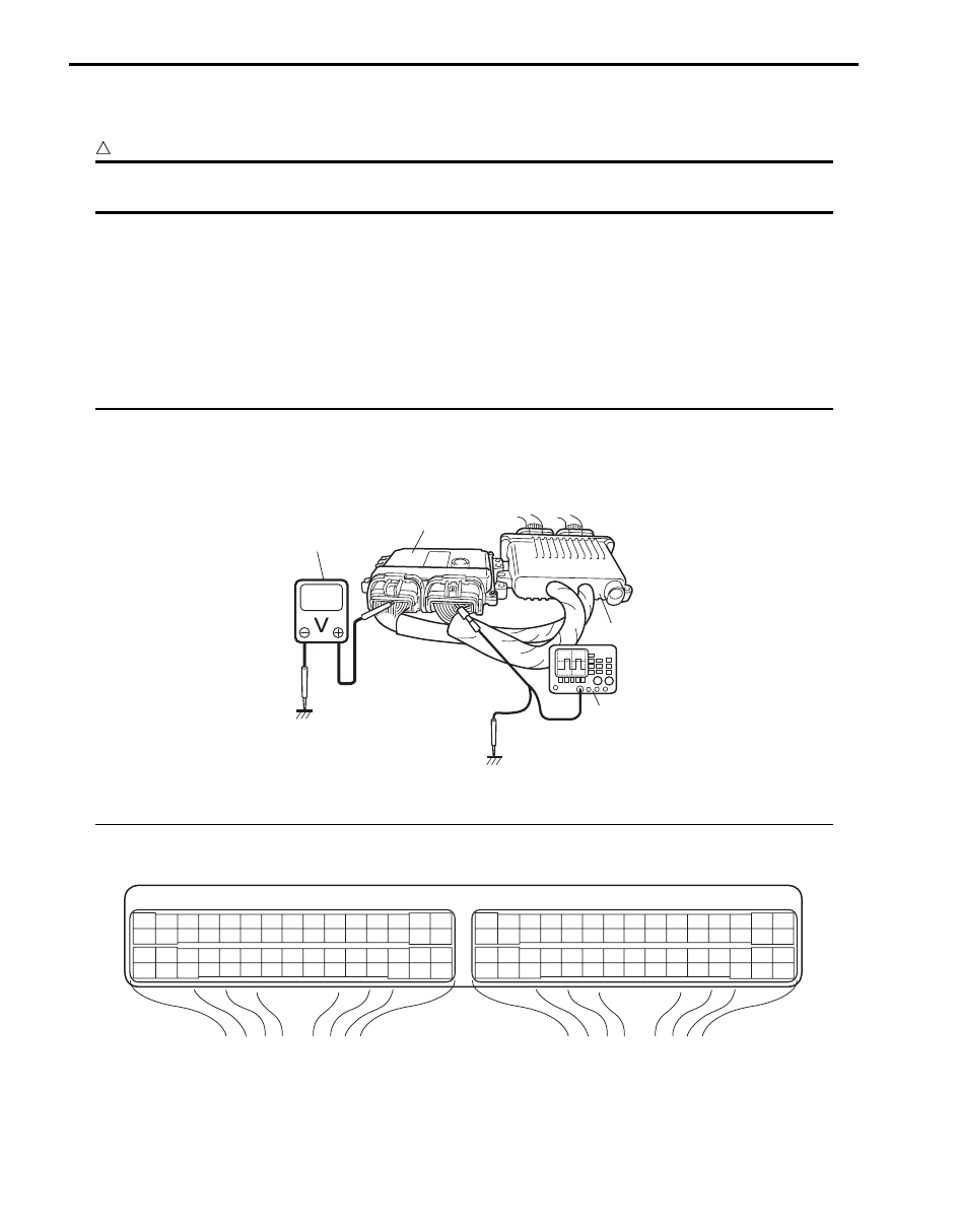
1) Remove ECM (1) from its bracket referring to “Engine Control Module (ECM) Removal and Installation in Section
1C in related manual”.
2) Connect special tool between ECM and ECM connectors securely.
Special tool
(A): 09933–06320
3) Check voltage and/or pulse signal using voltmeter (2) and oscilloscope (3).
NOTE
• As each terminal voltage is affected by battery voltage, confirm that it is 11 V or more when ignition
switch is turned ON.
• Voltage with asterisk (*) cannot be measured with voltmeter because it is pulse signal. Use
oscilloscope for its check if necessary.
• Before performed this inspection, be sure to read the “Precautions of ECM Circuit Inspection in
related manual”.
Viewed from harness side
1
2
3
(A)
I5JB0A110073-01
E23
C37
3
4
18
19
5
6
7
10
11
17
20
47
46
49
50
51
21
22
52
16
25
9
24
14
29
55
57
54 53
59
60
58
2
26
27
28
15
30
56
48
32
31
34
35
36
37
40
42
39 38
44
45
43
41
33
1
12
13
23
8
3
4
18
19
5
6
7
10
11
17
20
47
46
49
50
51
21
22
52
16
25
9
24
14
29
55
57
54 53
59
60
58
2
26
27
28
15
30
56
48
32
31
34
35
36
37
40
42
39 38
44
45
43
41
33
1
12
13
23
8
I4RS0A110055-01