Suzuki Grand Vitara JB627. Service manual - part 435
10E-25 Keyless Start System:
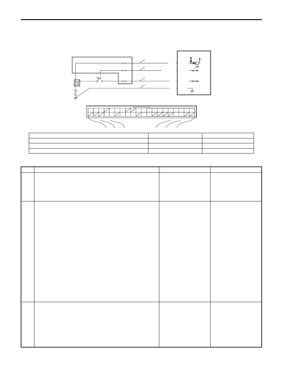
Keyless Start Control Module Power and Ground Circuit Check
S6JB0BA504016
Wiring Diagram
Troubleshooting
BLK G44-9
G44-15
G44-10
G44-11
WHT/BLK
WHT
YEL
5V
12V
G44
[A]
1
2
3
4
5
6
7
8
9
10
11
14
15
16
36
34 33 32
30 29
24 23
37
18
19
20
5
2
4
1
3
3
3
6
7
8
9
I7JB01A50003-01
[A]: Keyless start control module connector (viewed from harness side)
4. Main fuse
8. IG ON signal circuit
1. Keyless start control module
5. Junction block
9. Ground circuit
2. Ignition switch
6. Power source circuit
3. Circuit fuse
7. ACC signal circuit
Step
Action
Yes
No
1
Fuse check
1) Turn ignition switch to OFF position.
2) Check circuit fuse and main fuse for condition.
Are fuses in good condition?
Go to Step 2.
Replace fuse(s) and
check for short.
2
Power supply circuit check
1) Disconnect connector from keyless start control module.
2) Check for proper connection to “Power source”, “ACC
signal” and “IG ON signal” terminal of keyless start
control module connector.
3) If OK, measure voltage between following terminals.
• “Power source” terminal of keyless start control
module connector and vehicle body ground with
ignition switch is at OFF position
• “ACC signal” terminal of keyless start control module
connector and vehicle body ground with ignition
switch is at ACC position
• “IG ON signal” terminal of keyless start control module
connector and vehicle body ground with ignition
switch is at ON position
Is each terminal voltage is 10 – 14 V?
Go to Step 3.
Repair defective power
supply circuit.
3
Ground circuit check
1) Check for proper connection to “Ground” terminal of
keyless start control module connector.
2) If OK, measure resistance between “Ground” terminal of
keyless start control module connector and vehicle body
ground.
Is resistance 1
Ω
or less?
Power and ground
circuit is in good
condition.
Repair ground circuit.