Suzuki Grand Vitara JB627. Service manual - part 190
 

  Index      Suzuki     Suzuki Grand Vitara JB627 - service and repair manual


Search            


Content   ..  188  189  190  191   ..


Suzuki Grand Vitara JB627. Service manual - part 190


4E-41 ABS: 

Rear Wheel Speed Sensor Inspection

S6JB0B4506010

Refer to “Front Wheel Speed Sensor Inspection” since 
rear wheel speed sensor is the same as front wheel 
speed sensor.

Front Wheel Encoder On-Vehicle Inspection

S6JB0B4506011

Before inspect front wheel encoder, remove front drive 
shaft referring to “Front Drive Shaft Assembly Removal 
and Installation: Front in Section 3A”.
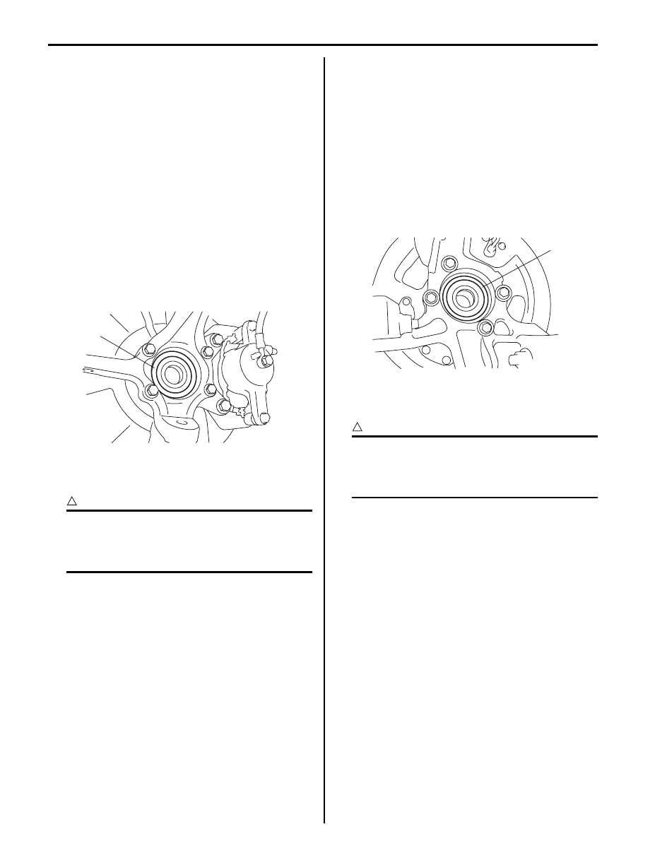
• Check encoder (1) for being crack, damaged or 

deformed.

• Turn wheel and check if encoder rotation is free from 

eccentricity and looseness.

• Check that no foreign material is attached.
If any faulty is found, repair or replace. Refer to “Front 
Wheel Hub Assembly Removal and Installation in 
Section 2B”.

Front Wheel Encoder Removal and Installation

S6JB0B4506012

CAUTION

!


Front wheel encoder is included in front 
wheel hub assembly. If front wheel encoder 
needs to replaced, replace it as a front wheel 
hub assembly.


For removal and installation of front wheel hub 
assembly, referring to “Front Wheel Hub Assembly 
Removal and Installation in Section 2B”.

Rear Wheel Encoder On-Vehicle Inspection

S6JB0B4506013

Before inspect rear wheel encoder, remove rear drive 
shaft referring to “Rear Drive Shaft Assembly Removal 
and Installation: Rear in Section 3A”.
• Check encoder (1) for being crack, damaged or 

deformed.

• Turn wheel and check if encoder rotation is free from 

eccentricity and looseness.

• Check that no foreign material is attached.

If any faulty is found, repair or replace. Refer to “Rear 
Wheel Hub Assembly Removal and Installation in 
Section 2C”.

Rear Wheel Encoder Removal and Installation

S6JB0B4506014

CAUTION

!


Rear wheel encoder is included in rear wheel 
hub assembly. If rear wheel encoder needs to 
replaced, replace it as a rear wheel hub 
assembly.


For removal and installation of front wheel hub 
assembly, referring to “Rear Wheel Hub Assembly 
Removal and Installation in Section 2C”.

1

I5JB0A450034-01

1

I5JB0A450035-01

ABS: 4E-42

Specifications

Tightening Torque Specifications

S6JB0B4507001

NOTE
The specified tightening torque is also described in the following.
“ABS (ESP

®) hydraulic unit / control module Assembly Components”


Reference:
For the tightening torque of fastener not specified in this section, refer to “Fastener Information in Section 0A”.

Special Tools and Equipment

Special Tool

S6JB0B4508001

Fastening part

Tightening torque

Note

N

m

kgf-m

lb-ft

Brake pipe flare nut (M10)

16

1.6 

11.5

)

Brake pipe flare nut (M12)

19

1.9 

14.0

)

ABS (ESP

®) hydraulic unit / control module 

assembly bolt

9

0.9 

6.5

)

ABS (ESP

®) hydraulic unit / control module 

assembly bracket bolt

25

2.5 18.0

)

ABS (ESP

®) hydraulic unit / control module 

assembly bracket nut

25

2.5 18.0

)

Front wheel speed sensor bolt

11

1.1 

8.0

)

Front wheel speed sensor harness clamp bolt 

11

1.1 

8.0

)

Rear wheel speed sensor bolt

11

1.1 

8.0

)

Rear wheel speed sensor harness clamp bolt

11

1.1 

8.0

)

09950–78220

SUZUKI scan tool

Flare nut wrench (10 mm)

)

This kit includes following 
items. 1. Tech 2, 2. PCMCIA 
card, 3. DLC cable, 4. SAE 
16/19 adapter, 5. Cigarette 
cable, 6. DLC loop back 
adapter, 7. Battery power 
cable, 8. RS232 cable, 9. 
RS232 adapter, 10. RS232 
loop back connector, 11. 
Storage case, 12. ) / )

4F-1 Electronic Stability Program: 

Brakes

Electronic Stability Program

Precautions

Precautions in Diagnosing Troubles

S6JB0B4600001

To ensure that the trouble diagnosis is done accurately 
and smoothly, observe the following and follow 
“Electronic Stability Program Check”.
• Diagnostic information stored in ESP

® control module 

memory can be cleared as well as checked by using 
SUZUKI scan tool. Before using scan tool, read its 
Operator’s (Instruction) Manual carefully to have good 
understanding as to what functions are available and 
how to use it.

• If the vehicles was operated in any of the following 

ways, ESP

® warning light may light momentarily but 

this does not indicate anything abnormal in ESP

®.

– The vehicle was driven with parking brake pulled.
– The vehicle was driven with brake dragging.
– The vehicle was stuck in mud, sand, etc.
– Wheel spin occurred while driving.
– Wheel(s) was rotated while the vehicle was jacked 

up.

• Be sure to read “Precaution for CAN Communication 

System in Section 00” before inspection and observe 
what is written there.

• Be sure to use the trouble diagnosis procedure as 

described in “Electronic Stability Program Check”. 
Failure to follow it may result in incorrect diagnosis. 
(Some other diagnosis trouble code may be stored by 
mistake in the memory of ESP

® control module 

during inspection.)

• When disconnecting ESP

® control module connector 

(1), pull up lock lever (2) of connector.
When connecting, set the connector on ESP

® 

hydraulic unit / control module assembly and pull 
down the lock lever (2) until it locks.

• Communication of ECM, TCM (A/T model), BCM, 

ESP

® (ABS) control module (if equipped), 4WD 

control module (if equipped), keyless start control 
module (if equipped) and combination meter is 
established by CAN (Controller Area Network).
Therefore, be sure to read “Precaution for CAN 
Communication System in Section 00”
 before 
inspection and handling CAN communication line.

Precautions in On-Vehicle Service

S6JB0B4600002

When connector is connected to ESP

® hydraulic unit / 

control module assembly, do not disconnect connectors 
of sensors with ignition switch ON. Otherwise, DTC will 
be set in ESP

® control module.

Precautions in Hydraulic Unit Operation Check

S6JB0B4600003

ESP

® hydraulic unit / control module assembly function 

is checked by correct wheel lock / release condition 
when brake pressure is pressurized / depressurized 
using SUZUKI scan tool. The hydraulic unit operation 
check referring to “Hydraulic Unit Operation Check in 
Section 4E” sho
uld be performed to confirm the correct 
brake pipe connection in the following cases.
• ESP

® hydraulic unit / control module assembly was 

replaced.

• Brake pipe and/or hose were replaced.

[A]: Disconnect

C: Pull up to disconnect

[B]: Connect

D: Pull down to connect

2

1

[A]

[B]

C

D

I6JB01460001-01

Electronic Stability Program:  4F-2

Precautions in Sensor Calibration

S6JB0B4600004

ESP

® control module stores calibration points data of yaw rate / G sensor assembly and master cylinder pressure 

sensor. Steering angle sensor stores calibration point data of itself.
TCS and stability control system use these sets of data.
When the following operation is done, calibration should be performed since the original calibration points are deleted.

Perform sensor calibration according to “Sensor Calibration”.

Precautions in Speedometer Test or Other Tests

S6JB0B4600005

When performing speedometer or a bench test while rotating a tire, ESP

® function must be kept at stop. It is possible 

to stop ESP

® function temporarily by ESP® OFF switch. In this case, however, the function is forced to come back to 

work when the speed exceeds 30km/h (18.5 mph) and may hinder accurate testing.
There are two ways to stop the ESP

® function completely as described bellow.

• Connect the SUZUKI scan tool, set to the “MISC. TEST” mode to stop the ESP

® function. Refer to SUZUKI scan 

tool operator’s manual for further details.

• Disconnect the connector of the steering angle sensor, and ESP

® function is forced to enter the fail-safe mode, 

then ESP

® function is stopped.

However, when this method is used, DTC remains in the memory of the ESP

® control module. Therefore, after the 

test, re-connect the connector, clear DTC in the memory of the ESP

® control module. And calibrate steering angle 

sensor referring to “Sensor Calibration”.

General Description

Electronic Stability Program Description

S6JB0B4601001

Electronic Stability Program (ESP

®) main function is to control ABS / EBD, TCS and stability.

• ABS / EBD

ABS function is that four wheel brake forces are independently varied with referring each wheel slip condition.
EBD function is that front and rear wheel braking forces are varied with referring loading distribution of the vehicle.
ABS improves the vehicle stability, controllability and braking performance.
For the details, refer to “ABS Description in Section 4E”.

• TCS (Traction Control System)

TCS function is that engine torque is controlled and brake is applied with referring wheel spin condition during 
vehicle starting and accelerating.

• Stability control system

Stability control system is that engine torque is controlled and brake is applied with referring vehicle condition (over 
steering, under steering) during cornering.

ESP

® is a registered trademark of Daimler Chrysler AG.

Sensor

Procedures required calibration

Steering angle sensor

• Power is not supplied to steering angle sensor. (battery and/or fuse is removed.)
• Steering angle sensor is replaced.
• Power is not supplied to ESP

® control module. (battery, fuse and/or connector is 

removed.)

• ESP

® hydraulic unit / control module assembly is replaced.

Master cylinder pressure sensor • ESP

® hydraulic unit / control module assembly is removed or replaced.

Yaw rate / G sensor assembly

• Yaw rate / G sensor assembly is removed or replaced.
• ESP

® hydraulic unit / control module assembly is replaced.


Content   ..  188  189  190  191   ..