Suzuki Grand Vitara JB627. Service manual - part 141
 

  Index      Suzuki     Suzuki Grand Vitara JB627 - service and repair manual


Search            


Content   ..  139  140  141  142   ..


Suzuki Grand Vitara JB627. Service manual - part 141


3B-6 Differential: Front

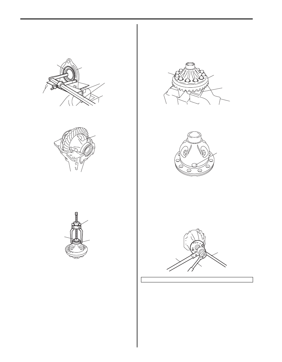
5) Support differential side right retainer (1) with soft 

jawed vise and remove oil seal (2) from differential 
side right retainer using special tool, if necessary.

Special tool
(A):  09913–50121

6) Take out differential assembly (1), outer race and 

shim all at once.

7) Pull out differential side bearing (1) using special 

tools.

Special tool
(A):  09913–65135
(B):  09925–86010

8) Remove drive bevel gear (hypoid gear), differential 

gears, differential pinions and pinion shaft as follows.
a) With aluminum plates (2) placed on vise first, 

grip differential case with it and remove drive 
bevel gear (hypoid gear) (3) by removing its bolts 
(1).

b) Remove pinion shaft (1), differential gears, 

washers, differential pinions, spring washers and 
thrust washers.

9) Remove drive bevel pinion (hypoid gear) assembly 

as follows.
a) Hold joint flange with special tool and then 

remove flange nut by using power wrench (4 – 
10 magnification) (2).

Special tool
(A):  09922–66021

1

(A)

2

I5JB0A321011-01

1

I5JB0A321012-02

1

(B)

(A)

I5JB0A321013-02

1. Socket wrench

3

2

1

I5JB0A321014-02

1

I5JB0A321015-02

(A)

2

1

I5JB0A321016-02

Differential: Front 3B-7

b) Make mating marks (1) on drive bevel pinion and 

companion flange.

CAUTION

!


Do not make mating mark on the coupling 
surface of the flange.


c) Remove flange (2) from drive bevel pinion. Use 

special tool if it is hard to remove.

Special tool
(A):  09913–65135
(B):  09925–88210

d) Remove drive bevel pinion (1) with rear bearing, 

shim and spacer from carrier.
If it is hard to remove, screw an used nut (2) into 
drive bevel pinion and hammer (3) on that nut 
with a plastic hammer but never directly on drive 
bevel pinion.

e) Remove drive bevel pinion rear bearing (2) by 

using bearing puller (3) and hydraulic press.

CAUTION

!


To avoid rear bearing from being damaged, 
support it at flat side of bearing puller.


10) Remove oil seal (1) using special tool.

Special tool
(A):  09913–50121

11) Using a hammer and brass bar (1), drive out front 

bearing outer race (2).

2

(B)

(A)

2

1

I5JB0A321017-02

3

2

1

I5JB0A321018-01

1. Drive bevel pinion

I1JA01322006-01

(A)

1

I5JB0A321019-01

I5JB0A321020-01

3B-8 Differential: Front

12) Drive out rear bearing outer race (1) in the same 

manner as Step 11).

Reassembly
Judging from faulty conditions noted before disassembly 
and what is found through visual check of bearing and 
gear tooth etc. after disassembly, prepare replacing 
parts and proceed to reassembly according to 
procedures as described.

CAUTION

!


• Drive bevel gear and pinion must be 

replaced as a set when either replacement 
becomes necessary.

• When replacing taper roller bearing, 

replace as inner race and outer race 
assembly.


1) For press-fitting drive bevel pinion bearing outer 

races, use special tools and press as shown in the 
figure.

Special tool
(A):  09924–74510
(B):  09925–14520
(C):  09913–75510

2) After applying differential oil to differential gear (4), 

pinions (5), pinion shaft (6), pinion washer, thrust 
washer (2) and spring washer (1), install them in 
differential right case (3).
For correct installing direction of thrust washer (2) 
and spring washer (1), refer to the figure.

3) Check differential pinion gear (1) for smooth rotation.

4) Put drive bevel gear (3) on differential case (1) and 

fasten them with bolts (2) by tightening them to 
specified torque. Use thread lock cement for bolts 
(2).

CAUTION

!


Use of any other bolts than that specified is 
prohibited.


“A”:  Thread lock cement 99000–32110 (Thread 
Lock Cement Super 1322) 

Tightening torque
Bevel gear bolt (a):  Tighten 40 N

m (4.0 kgf-m, 

29.5 lb-ft) + 50

° 

1. Differential carrier

I5JB0A321021-01

(B)

(A)

1

(C)

I5JB0A321022-01

I5JB0A321023-05

1

I5JB0A321024-04

2, (a), “A”

3

1

I5JB0A321025-01

Differential: Front 3B-9

5) Install special tool to differential case assembly (2) 

and check that preload is within specification. If 
preload exceeds specified value, check if foreign 
matter is caught or gear is damaged.

Special tool
(B):  09928–06510

Side gear preload
Max. 2.5 N

m (0.25 kgf-m, 1.8 lb-ft)

6) Press-fit left side bearing (1) with special tool and 

hydraulic press.

Special tool
(A):  09913–75821
(B):  09924–84510–004

7) Press-fit right side bearing (1) with special tools and 

hydraulic press.

NOTE
Be sure to use bearing holder for the purpose 
of protecting lower bearing.


Special tool
(A):  09913–75821
(B):  09924–84510–004
(C):  09924–84510–005

1. Torque wrench
3. Aluminum plate
4. Vise

I5JB0A321026-01

(B)

(A)

1

I5JB0A321027-01

(B)

(A)

1

(C)

I5JB0A321028-02


Content   ..  139  140  141  142   ..