Suzuki Grand Vitara JB627. Service manual - part 125
 

  Index      Suzuki     Suzuki Grand Vitara JB627 - service and repair manual


Search            


Content   ..  123  124  125  126   ..


Suzuki Grand Vitara JB627. Service manual - part 125


2B-14 Front Suspension: 

Assembly

CAUTION

!


Apply grease (included in the repair kit) to 
ball joint and inside of ball stud boot when 
the ball stud boot is replaced.


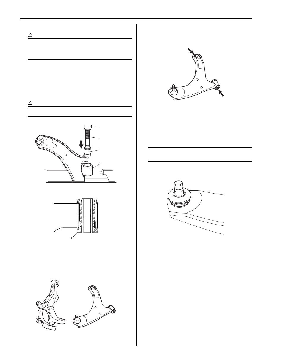
1) Front bushing

Press-fit front bushing (1) by using special tools and 
press (2).

Special tool
(A):  09945–55410
(B):  09913–75821

CAUTION

!


Be sure to use new bushing.


2) Install rubber stopper (1).

Suspension Control Arm / Steering Knuckle 
Check

S6JB0B2206012

Inspect for cracks, deformation or damage.
If defective, replace.

Suspension Control Arm Bushing Check

S6JB0B2206013

Inspect for damage, wear or deterioration.
If defective, replace.

Suspension Control Arm Joint Check

S6JB0B2206014

• Check smooth rotation of ball stud.
• Check damages of ball stud.
• Check damages of dust cover.

NOTE
Suspension control arm and arm joint cannot 
be separated.


If there is any damage to either parts, control arm 
assembly must be replaced as a complete unit.

2

(B)

1

(A)

I5JB0A220036-01

I5JB0A220037-01

I5JB0A220038-01

I5JB0A220039-01

I4RS0B220023-01

Front Suspension:  2B-15

Front Suspension Frame, Stabilizer Bar and/or Bushings Components

S6JB0B2206015

10

7

3

2

5

1

8

8

7

(a)

4

6

(b)

9

(b)

9

11

(b)

F

(c)

(d)

12

I6JB01220006-01

F: Forward

6. Stabilizer joint nut

12. Stabilizer mount

1. Stabilizer bar

7. Suspension control arm

: 50 N

⋅m (5.0 kgf-m, 36.5 lb-ft)

2. Stabilizer bushing

8. Control arm mounting bolt

: 135 N

⋅m (13.5 kgf-m, 98.0 lb-ft)

3. Stabilizer mounting bracket

9. Control arm nut

: 60 N

⋅m (6.0 kgf-m, 43.5lb-ft)

4. Stabilizer bar mounting bracket bolt

10. Suspension frame

: 55 N

⋅m (5.5 kgf-m, 40.0 lb-ft)

5. Stabilizer joint

11. Suspension frame mounting bolt

: If bolt and nut is reused, apply engine oil to thread, 

bearing and trunk surface.

2B-16 Front Suspension: 

Front Suspension Frame, Stabilizer Bar and/or 
Bushings Removal and Installation

S6JB0B2206016

WARNING

!


When removing and installing front 
suspension frame, be sure to apply some 
supporting equipment under it at well-
balanced position to prevent from its drop. 
Otherwise, drop and injure.


Removal

1) Hoist vehicle and remove wheels (right & left).
2) Remove engine under cover.
3) Remove suspension control arm referring to 

“Suspension Control Arm Removal and Installation”.

4) Remove right side and left side front drive shaft 

assembly referring to “Front Drive Shaft Assembly 
Removal and Installation: Front in Section 3A”
.

5) Remove stabilizer joints (1). When loosening joint 

nut, hold stud with hexagon wrench.

6) Disconnect front fender lining clip (1) (if equipped 

with head light auto leveling system).

7) Disconnect front height sensor connector (1) (if 

equipped with head light auto leveling system) and 
then detach clip (2).

8) Disconnect steering lower shaft from pinion shaft 

referring to “P/S Gear Case Assembly Removal and 
Installation in Section 6C”
.

9) Detach P/S oil line from suspension frame and P/S 

gear case assembly referring to the figure in “P/S 
Hose / Pipe Components in Section 6C”
.

10) Remove front propeller shaft referring to “Propeller 

Shaft Removal and Installation in Section 3D”.

11) Fix radiator (2) to body with rope (1) to avoid the 

radiator (2) fall off when front suspension frame 
lowered.

1

1

I5JB0A220041-01

1

I5JB0A220042-01

1

2

I5JB0A220043-01

1

2

I5JB0A220046-01

Front Suspension:  2B-17

12) Support engine assemble as follows.

a) Remove hood referring to “Hood Removal and 

Installation in Section 9J”.

b) Support engine assemble by using chain hoist.

13) Support suspension frame at the specified positions 

(1) indicated in figure.

14) Remove engine front body side mounting nuts (1).
15) Remove suspension frame mounting bolts (2), and 

then lower suspension frame (3) with stabilizer bar, 
P/S gear box assembly and front differential 
assembly.

16) Remove P/S gear box assembly (1) and front 

differential assembly (2) referring to “P/S Gear Case 
Assembly Removal and Installation in Section 6C” 
and “Front Differential Dismounting and Remounting: 
Front in Section 3B”
.

17) Remove stabilizer bar (1) and bushing (2) from 

suspension frame (3).

1

1

I5JB0A220047-01

1

2

2

3

I6JB01220007-01

1

2

I5JB0A220049-01

1

2

2

3

I5JB0A220050-01


Content   ..  123  124  125  126   ..