Suzuki Grand Vitara JB627. Service manual - part 119
 

  Index      Suzuki     Suzuki Grand Vitara JB627 - service and repair manual


Search            


Content   ..  117  118  119  120   ..


Suzuki Grand Vitara JB627. Service manual - part 119


1K-2 Exhaust System: 

Repair Instructions

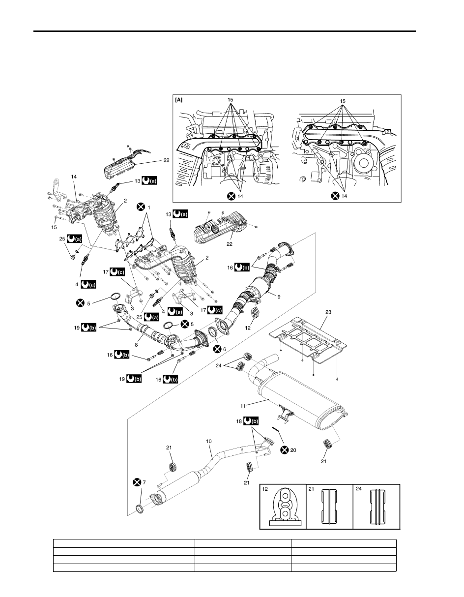
Exhaust System Components

S6JB0B1B06001

I6JB0B1B0001-01

[A]: Installing location of exhaust manifold bolt and nut

10. Exhaust center pipe

20. Muffler gasket

1. Exhaust manifold gasket

11. Muffler

21. Mounting No.2

2. Exhaust manifold

12. Mounting No.1

22. Exhaust manifold cover

3. Exhaust manifold stiffener

13. A/F sensor

23. Heat protector rear panel

Exhaust System:  1K-3

Exhaust Manifold Removal and Installation

S6JB0B1B06002

WARNING

!


To avoid danger of being burned, do not 
service exhaust system while it is still hot. 
Service should be performed after system 
has cooled off.


Removal
Right side exhaust manifold

1) Remove battery and battery tray.
2) Remove air cleaner assembly and air cleaner outlet 

hose.

3) Remove A/F sensor connector (1) and HO2S 

connector (2) (if equipped) from bracket, then 
disconnect them.

4) For RHD model, remove steering lower shaft 

assembly referring to “Steering Lower Shaft 
Assembly Removal and Installation in Section 6B”.

5) If equipped with EGR system, disconnect EGR pipe 

(3) from exhaust manifold.

6) Remove exhaust manifold cover.
7) Remove exhaust No.1 pipe.
8) Remove exhaust manifold stiffener (1).

9) Remove exhaust manifold (1) and its gasket from 

cylinder head.

Left side exhaust manifold

1) Release fuel pressure in fuel feed line referring to 

“Fuel Pressure Relief Procedure in Section 1G”.

2) Disconnect negative (–) cable at battery.
3) Disconnect fuel feed hose (1) and fuel return hose 

(2).

4) Disconnect brake booster hose (1), vacuum tank 

hose (2) and EVAP canister purge valve hose (3) 
from intake manifold and fuel No.2 pipe (4).

4. HO2S (if equipped)

14. Exhaust manifold bolt

24. Mounting No.3

5. Exhaust No.1 pipe gasket

15. Exhaust manifold nut

25. Plug (if equipped)

6. No.1 seal ring

16. Exhaust pipe bolt

: 45 N

⋅m (4.5 kgf-m, 32.5 lb-ft)

7. No.2 seal ring

17. Exhaust manifold stiffener bolt

: 50 N

⋅m (5.0 kgf-m, 36.5 lb-ft)

8. Exhaust No.1 pipe

18. Muffler nut

: 30 N

⋅m (3.0 kgf-m, 21.5 lb-ft)

9. Exhaust No.2 pipe 

19. Exhaust pipe nut

: Do not reuse.

3

1

2

I6JB011B0003-01

1

I6JB011B0004-01

1

I6JB011B0005-01

1

2

I6JB011B0006-01

1

2

4

3

I6JB011B0007-01

1K-4 Exhaust System: 

5) Disconnect vacuum hose from IMT valve, and 

remove vacuum tank assembly.

6) For LHD model, remove steering lower shaft 

assembly referring to “Steering Lower Shaft 
Assembly Removal and Installation in Section 6B”.

7) Disconnect suction hose and discharge hose from A/

C compressor referring to “Compressor Assembly 
Removal and Installation in Section 7B”.

8) Remove oil filter referring to “Engine Oil and Filter 

Change in Section 0B”.

9) Remove A/F sensor connector (1) and HO2S 

connector (2) (if equipped) from bracket, then 
disconnect them.

10) Remove engine hook (1).

11) Remove oil level gauge (2) and oil level gauge guide 

(3).

12) Remove exhaust manifold cover (4).

13) Remove exhaust No.1 pipe.
14) Remove exhaust manifold stiffener (1).

15) Remove exhaust manifold (1) and its gasket from 

cylinder head.

Installation
Right side exhaust manifold
Reverse removal procedure for installation noting the 
following.
• Use new gaskets and seal rings.
• Always install new exhaust manifold bolts (1) with pre-

coated adhesive.

• Tighten each bolts and nuts to specified torque.

Tightening torque
Exhaust manifold stiffener bolt (a):  30 N·m (3.0 
kgf-m, 21.5 lb-ft)
Exhaust No.1 pipe bolt and nut (b):  50 N·m (5.0 
kgf-m, 36.5 lb-ft)

• For RHD model, install steering lower shaft assembly 

referring to “Steering Lower Shaft Assembly Removal 
and Installation in Section 6B”
.

• Upon completion of installation, start engine and 

check that no exhaust gas leakage exists.

1

2

I6JB011B0008-01

2

1

3

4

I6JB011B0009-01

1

I6JB011B0010-01

1

I6JB011B0011-01

1, (a)

 (b)

(b)

I6JB011B0012-02

Exhaust System:  1K-5

Left side exhaust manifold
Reverse removal procedure for installation noting the 
following.
• Use new gaskets and seal rings.
• Always install new exhaust manifold bolts (1) with pre-

coated adhesive.

• Tighten each bolts and nuts to specified torque.

Tightening torque
Exhaust manifold stiffener bolt (a):  30 N·m (3.0 
kgf-m, 21.5 lb-ft)
Exhaust No.1 pipe bolt and nut (b):  50 N·m (5.0 
kgf-m, 36.5 lb-ft)
HO2S:  45 N·m (4.5 kgf-m, 32.5 lb-ft)

• Install oil filter referring to “Engine Oil and Filter 

Change in Section 0B”.

• Connect suction hose and discharge hose to A/C 

compressor referring to “Compressor Assembly 
Removal and Installation in Section 7B”.

• For LHD model, install steering lower shaft assembly 

referring to “Steering Lower Shaft Assembly Removal 
and Installation in Section 6B”
.

• Upon completion of installation, turn ignition switch to 

ON position and check that no fuel leakage.

• Start engine and check that no exhaust gas leakage.

Muffler Removal and Installation

S6JB0B1B06003

WARNING

!


To avoid the danger of being burned, do not 
touch the exhaust system when the system is 
hot. Any service on the exhaust system 
should be performed when the system is 
cool.


CAUTION

!


Three way catalytic converter should not be 
exposed to any impulse. Be careful not to 
drop it or hit it against something.


Refer to “Exhaust System Components”.

Specifications

Tightening Torque Specifications

S6JB0B1B07001

NOTE
The specified tightening torque is also described in the following.
“Exhaust System Components”


Reference:
For the tightening torque of fastener not specified in this section, refer to “Fastener Information in Section 0A”.

1, (a)

(b)

I6JB011B0013-02

Fastening part

Tightening torque

Note

N

m

kgf-m

lb-ft

Exhaust manifold stiffener bolt

30

3.0 

21.5

)

 / )

Exhaust No.1 pipe bolt and nut

50

5.0 

36.5

)

 / )

HO2S

45

4.5 32.5

)


Content   ..  117  118  119  120   ..