Suzuki Grand Vitara JB627. Service manual - part 87
 

  Index      Suzuki     Suzuki Grand Vitara JB627 - service and repair manual


Search            


Content   ..  85  86  87  88   ..


Suzuki Grand Vitara JB627. Service manual - part 87


1D-29 Engine Mechanical: 

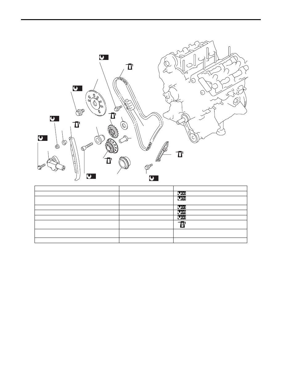
1st Timing Chain and Chain Tensioner Components

S6JB0B1406021

(a)

13

(c)

15

17

(e)

16

(b)

18

(b)

19

1

3

7

5

8

10

14

2

9

6

12

11

4

(a)

(c)

(d)

(b)

(b)

(e)

OIL

OIL

OIL

OIL

OIL

I6JB01140053-01

1. 1st timing chain

10. Timing chain tensioner

19. Timing chain guide No.2 bolt

2. Timing chain tensioner adjuster No.1

11. Timing chain guide No.1

: 80 N

⋅m (8.0 kgf-m, 58.0 lb-ft)

3. RH (No.2) bank 1st timing chain intake camshaft 

sprocket

12. Timing chain guide No.2

: 9 N

⋅m (0.9 kgf-m, 6.5 lb-ft)

4. 1st timing chain crankshaft sprocket

13. Camshaft sprocket bolt

: 25 N

⋅m (2.5 kgf-m, 18.0 lb-ft)

5. Idler sprocket No.2

14. Spacer

: 55 N

⋅m (5.5 kgf-m, 40.0 lb-ft)

6. Shaft

15. Timing chain tensioner nut

: 11 N

⋅m (1.1 kgf-m, 8.0 lb-ft)

7. Idler sprocket No.1

16. Idler sprocket No.1 bolt

: Apply engine oil to sliding parts.

8. Shaft

17. Timing tensioner adjuster No.1 

bolt

9. Washer

18. Timing chain guide No.1 bolt

Engine Mechanical:  1D-30

1st Timing Chain and Chain Tensioner Removal 
and Installation

S6JB0B1406022

Removal

1) Remove engine assembly from vehicle. Refer to 

“Engine Assembly Removal and Installation”.

2) Remove timing chain cover. Refer to “Timing Chain 

Cover Removal and Installation”.

3) For reinstallation of timing chain, align 8 timing 

marks as shown in figure by turning crankshaft.

4) Remove LH (No.1) bank 2nd timing chain. Refer to 

“LH (No.1) Bank 2nd Timing Chain and Chain 
Tensioner Removal and Installation”.

5) Remove the following parts referring to “1st Timing 

Chain and Chain Tensioner Components”.
• Timing chain guide No.1 and No.2.
• Timing chain tensioner.
• Timing chain tensioner adjuster.
• Idler sprocket No.1 and 1st timing chain.
• Idler sprocket No.2 and sprocket shaft.

6) Remove RH (No.2) bank 1st timing chain intake 

camshaft sprocket bolt. To remove it, fit a spanner to 
hexagonal part (3) at the center of camshaft (2) to 
hold it stationary.

7) Remove RH (No.2) bank 1st timing chain intake 

camshaft sprocket (1).

8) Remove 1st timing chain crankshaft sprocket.

Installation

1) Check timing pulley key (1) of crankshaft is on 

specified position as shown in figure.

2) Install 1st timing chain crankshaft sprocket (2) to 

crankshaft as shown in figure.

3) Check timing mark on RH (No.2) bank intake 

camshaft as shown in figure.

I6JB01140054-01

I6JB01140055-01

3. Crankshaft pulley side

4. Oil pump sprocket side

5. Oil jet

1. Knock pin of intake camshaft

2. Match mark

2

3

4

5

1

I6JB01140056-01

IYSQ01143069-01

1D-31 Engine Mechanical: 

4) Install RH (No.2) bank 1st timing chain intake 

camshaft sprocket (1) noting the following points.
• The sprocket should be set in such way that its 

timing marks (4) can be seen.

• Camshaft (2) should be held stationary by using a 

spanner at its hexagonal parts (3) as shown in 
figure.

Tightening torque
RH (No.2) bank 1st timing chain intake 
camshaft sprocket bolt (a):  80 N·m (8.0 kgf-m, 
58.0 lb-ft)

5) Install timing chain tensioner (1) as shown in figure.

Tightening torque
Timing chain tensioner nut (b):  25 N·m (2.5 kgf-
m, 18.0 lb-ft)

6) Install 1st timing chain by aligning match marks (2) 

on RH silver plate (1) of 1st timing chain and RH 
(No.2) bank 1st timing chain intake camshaft 
sprocket (3).

7) Apply oil to bush of idler sprocket No.2.
8) Install idler sprocket No.2 and sprocket shaft.
9) Install idler sprocket No.2 by aligning match marks 

(2) on LH silver plate (1) of 1st timing chain.

10) Install crankshaft sprocket by aligning match marks 

(2) on yellow plate (1) of 1st timing chain and 
crankshaft timing sprocket.
To install it, fit a spanner to hexagonal part at the 
center of RH (No.2) bank intake camshaft to turn a 
little.

CAUTION

!


Do not turn camshaft more than necessary. If 
turned excessively, valve and piston may get 
damaged.


2. Spacer

3. RH (No.2) bank cylinder head

I6JB01140057-01

I6JB01140058-01

4. RH (No.2) bank cylinder head

3. LH (No.1) bank cylinder head

3. Crankshaft

I6JB01140059-01

IYSQ01143073-01

IYSQ01143074-01

Engine Mechanical:  1D-32

11) Apply oil to bearing of idler sprocket No.1.

12) Install idler sprocket No.1.

Tightening torque
Idler sprocket No.1 bolt (c):  55 N·m (5.5 kgf-m, 
40.0 lb-ft)

13) With latch of tensioner adjuster No.1 returned and 

plunger (1) pushed back into body, insert stopper (3) 
into latch (2) and body.
After inserting it, check to make sure that plunger (1) 
will not come out.

14) Install timing chain tensioner adjuster No.1 (1).

Tightening torque
Timing chain tensioner adjuster No.1 bolt (a):  11 
N·m (1.1 kgf-m, 8.0 lb-ft)

15) Pull out stopper (3) from adjuster No.1 (1).

16) Install timing chain guide No.1 (2) and No.2 (1).

Tightening torque
Timing chain guide No.1 and No.2 bolt (a):  9 N·m 
(0.9 kgf-m, 6.5 lb-ft)

IYSQ01143075-01

2

1

3

2

I6JB01140060-01

2. Timing chain tensioner

3. Guide bolt

1

(a)

2

3

I6JB01140061-01

(a)

2

1

(a)

3

I6JB01140113-01


Content   ..  85  86  87  88   ..