Suzuki Grand Vitara JB627. Service manual - part 53
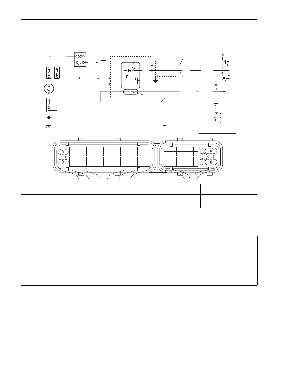
1A-161 Engine General Information and Diagnosis:
DTC P2195 / P2196: O2 Sensor Signal Stuck Lean / Stuck Rich (Sensor-1, Bank-1)
S6JB0B1104067
System and Wiring Diagram
A/F Sensor Description
Refer to “A/F Sensor Description”
DTC Detecting Condition and Trouble Area
4
3
9
PNK
6
2
1
d
a
b
8
5
BLK/WHT
BLK
PNK
GRN
C37-16
C37-77
C37-19
C37-18
BLK
BLK
BLU
WHT
C37-17
C37-79
BLK
WHT
RED/YEL
RED/BLU
PNK/BLK
BLK/YEL
10
7
11
5 V
5 V
1
3 2
4
5
6
7
8
9
1110
12
13
14
15
16
17
18
19
20
17
18
19
20
21
22
23
24
25
26
27
28
29
30
31
33
34
35
36
37
38
39
40
32
1
2
3
4
5
6
7
8
9
10
11
12
13
14
15
16
21
22
23
24
25
26
27
28
29
30
31
32
33
34
35
36
37
38
39
40
41
42
43
44
45
46
47
48
49
50
51
52
53
54
55
56
57
58
59
60
61
62
63
64
65
66
67
68
69
70
71
72
73
74
75
76
77
78
79
80
81
c
I6JB01110102-01
a. Signal (+) circuit of A/F sensor (bank-1)
1. HO2S heater relay
5. IG COIL fuse
9. ECM
b. Signal (–) circuit of A/F sensor (bank-1)
2. Shield wire
6. A/F sensor
10. Adjusting resistor (if equipped)
c. Adjusting resistor (+) circuit of A/F sensor (bank-1)
3. Ignition Switch
7. A/F sensor heater
11. A/F sensor element
d. Adjusting resistor (–) circuit A/F sensor (bank-1)
4. O2 HTR fuse
8. To A/F sensor (bank-2),
HO2S (bank-1 and -2)
DTC detecting condition
Trouble area
DTC P2195 O2 Sensor Signal Stuck Lean (Sensor-1, Bank-1):
Short term fuel trim is higher than 130% for 30 seconds even though
HO2S (bank-1) signal voltage is higher than 0.5 V.
(2 driving cycle detection logic)
DTC P2196 O2 Sensor Signal Stuck Rich (Sensor-1, Bank-1):
Short term fuel trim is lower than 70% for 30 seconds even though
HO2S (bank-1) signal voltage is lower than 0.5 V.
(2 driving cycle detection logic)
• A/F sensor circuit
• A/F sensor
• ECM