Suzuki Grand Vitara JB627. Service manual - part 28
 

  Index      Suzuki     Suzuki Grand Vitara JB627 - service and repair manual


Search            


Content   ..  26  27  28  29   ..


Suzuki Grand Vitara JB627. Service manual - part 28


1A-61 Engine General Information and Diagnosis: 

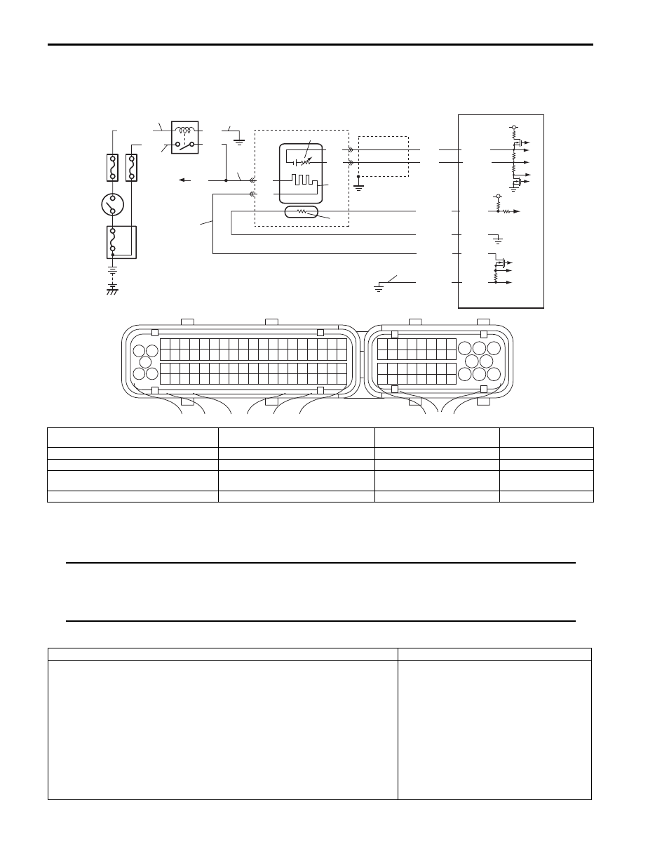
DTC P0031 / P0032: HO2S Heater Control Circuit Low / High (Sensor-1, Bank-1)

S6JB0B1104014

System and Wiring Diagram

A/F Sensor Description
Refer to “A/F Sensor Description”

NOTE
When DTC P0031, P0037, P0051 and P0057 are indicated together, it is possible that HO2S heater relay 
circuit wire is open or short to ground.
When DTC P0032, P0052 are indicated together, it is possible that A/F sensor heater ground circuit is 
open or high resistance.


DTC Detecting Condition and Trouble Area

4

3

9

PNK

6

2

1

e

f

d

a

b

8

5

BLK/WHT

BLK

PNK

GRN

C37-16

C37-77

C37-19

C37-18

BLK

BLK

BLU

WHT

C37-17

C37-79

BLK

WHT

RED/YEL

RED/BLU

PNK/BLK

BLK/YEL

10

7

11

5 V

5 V

1

3 2

4

5

6

7

8

9

1110

12

13

14

15

16

17

18

19

20

17

18

19

20

21

22

23

24

25

26

27

28

29

30

31

33

34

35

36

37

38

39

40

32

1

2

3

4

5

6

7

8

9

10

11

12

13

14

15

16

21

22

23

24

25

26

27

28

29

30

31

32

33

34

35

36

37

38

39

40

41

42

43

44

45

46

47

48

49

50

51

52

53

54

55

56

57

58

59

60

61

62

63

64

65

66

67

68

69

70

71

72

73

74

75

76

77

78

79

80

81

c

I6JB01110001-01

a. Power supply circuit of A/F sensor (bank-1) 

heater

f. Power supply circuit of HO2S heater relay 5. IG COIL fuse

10. Adjusting resistor (if 

equipped)

b. Control circuit of A/F sensor (bank-1) heater

1. HO2S heater relay

6. A/F sensor

11. A/F sensor element

c. Ground circuit of A/F sensor (bank-1) heater

2. Shield wire

7. A/F sensor heater

d. Ground circuit of HO2S heater relay coil

3. Ignition Switch

8. To A/F sensor (bank-2), HO2S 

(bank-1 and -2) (if equipped)

e. Power supply circuit of HO2S heater relay coil

4. O2 HTR fuse

9. ECM

DTC detecting condition

Trouble area

DTC P0031 HOS Heater Control Circuit Low (Sensor-1, Bank-1):
Circuit current of A/F sensor (bank-1) heater is lower than 0.8 A for more 
than 4 sec. continuously while control duty ratio of A/F sensor heater is 
more than 22% with engine running.
(2 driving cycle detection logic)
DTC P0032 HOS Heater Control Circuit High (Sensor-1, Bank-1):
Circuit current of A/F sensor (bank-1) heater is higher than 10.5 A at ON 
duty pulse or 0.8 A at OFF duty pulse for more than 4 sec. continuously 
while control duty ratio of A/F sensor heater is more than 22% with engine 
running.
(2 driving cycle detection logic)

• A/F sensor heater circuit
• A/F sensor
• ECM

Engine General Information and Diagnosis:  1A-62

DTC Confirmation Procedure 

1) With ignition switch turned OFF, connect scan tool to DLC.
2) Turn ON ignition switch and clear DTC.
3) Start engine and warm up to normal operating temperature.
4) Run engine at idle speed for 1 min. or more.
5) Check DTC and pending DTC.

DTC Troubleshooting

NOTE
Before this trouble shooting is performed, read the precautions for DTC troubleshooting referring to 
“Precautions for DTC Troubleshooting”.


Step

Action

Yes

No

1

Was “Engine and Emission Control System Check” 
performed?

Go to Step 2.

Go to “Engine and 
Emission Control 
System Check”.

2

A/F sensor heater circuit check
1) Disconnect connector from A/F sensor (bank-1) with 

ignition switch turned OFF.

2) Check for proper terminal connection to A/F sensor 

(bank-1) connector.

3) If connections are OK, measure circuit voltage between 

“Power supply circuit of A/F sensor (bank-1) heater” and 
vehicle body ground with ignition switch turned ON.

Is measured voltage 10 – 14 V?

Go to Step 7.

Go to Step 3.

3

HO2S heater fuse check
1) Check for “O2 HTR” fuse (1) blown.

Is “O2 HTR” fuse in good condition?

Go to Step 6.

Go to Step 4.

1

I5JB0C110009-01

1A-63 Engine General Information and Diagnosis: 

4

HO2S heater relay power circuit check
1) Disconnect connector from each A/F sensor and HO2S 

with ignition switch turned OFF.

2) Remove HO2S heater relay (integration type relay) (1) 

and then check for proper terminal connection to relay 
connector.

3) If connections are OK, check that HO2S heater relay 

circuit is as follows.
• Insulation resistance between “Power supply circuit of 

A/F sensor (bank-1) heater” and vehicle body ground 
is infinity.

• Insulation resistance between “Power supply circuit of 

HO2S heater relay” and vehicle body ground is 
infinity.

Is it in good condition?

Go to Step 5.

Repair or replace 
defective wiring 
harness.

5

A/F sensor and HO2S heater resistance check
1) Check heater resistance of each A/F sensor and HO2S 

referring to “Air Fuel Ratio (A/F) Sensor On-Vehicle 
Inspection in Section 1C” 
and “Heated Oxygen Sensor 
(HO2S-2) Heater On-Vehicle Inspection (If Equipped) in 
Section 1C”
.

Are each A/F sensor heater and HO2S heater in good 
condition?

Faulty HO2S heater 
relay. Check HO2S 
heater relay referring to 
“Engine and Emission 
Control System Relay 
Inspection in Section 
1C”.

Replace defective 
sensor.

Step

Action

Yes

No

1

I5JB0C110010-01

Engine General Information and Diagnosis:  1A-64

6

HO2S heater relay power circuit check
1) Disconnect connector from each A/F sensor and HO2S 

with ignition switch turned OFF.

2) Remove HO2S heater relay (integration type relay) (1) 

and then check for proper terminal connection to relay 
connector.

3) If connections are OK, check that HO2S heater relay 

circuit is as follows.
• Circuit voltage between “Power supply circuit of HO2S 

heater relay” and vehicle body ground is battery 
voltage with ignition switch turned ON.

• Circuit voltage between “Power supply circuit of HO2S 

heater relay coil” and vehicle body ground is battery 
voltage with ignition switch turned ON.

• Wiring harness resistance of each “Ground circuit of 

HO2S heater relay coil” and “Power supply circuit of 
A/F sensor (bank-1) heater” is less than 1 

Ω.

Are they in good condition?

Faulty HO2S heater 
relay. Check HO2S 
heater relay referring to 
“Engine and Emission 
Control System Relay 
Inspection in Section 
1C”.

Repair or replace 
defective wiring 
harness.

7

A/F sensor heater circuit check
1) Check that A/F sensor heater control circuit is as follows.

• Circuit voltage between “Control circuit of A/F sensor 

(bank-1) heater” and vehicle body ground is 0 V with 
ignition switch turned ON.

Is it good condition?

Go to Step 8.

repair or replace 
defective wiring 
harness.

8

A/F sensor heater circuit check
1) Disconnect connectors form ECM and check for proper 

terminal connection to ECM connector.

2) If connections are OK, check that A/F sensor heater 

circuit is as follows.
• Insulation resistance of wire harness is infinity 

between “Control circuit of A/F sensor (bank-1) 
heater” terminal and each other terminal at A/F sensor 
(bank-1) connector.

• Wiring harness resistance of “Control circuit of A/F 

sensor (bank-1) heater” and “Control ground circuit of 
A/F sensor (bank-1) heater” is less than 1 

Ω.

• Insulation resistance between “Control circuit of A/F 

sensor (bank-1) heater” and “Control ground circuit of 
A/F sensor (bank-1) heater” is infinity.

Are they in good condition?

Go to Step 9.

Repair or replace 
defective wiring 
harness.

Step

Action

Yes

No

1

I5JB0C110010-01


Content   ..  26  27  28  29   ..