Suzuki Grand Vitara JB416 / JB420. Service manual - part 369
 

  Index      Suzuki     Suzuki Grand Vitara JB416 / JB420- service and repair manual


Search            


Content   ..  367  368  369  370   ..


Suzuki Grand Vitara JB416 / JB420. Service manual - part 369


9B-15 Lighting Systems: 

Inspection of Headlight Leveling Control Module and Its Circuit (Vehicle Equipped With Auto 
Leveling Headlight System)

S5JB0A9204021

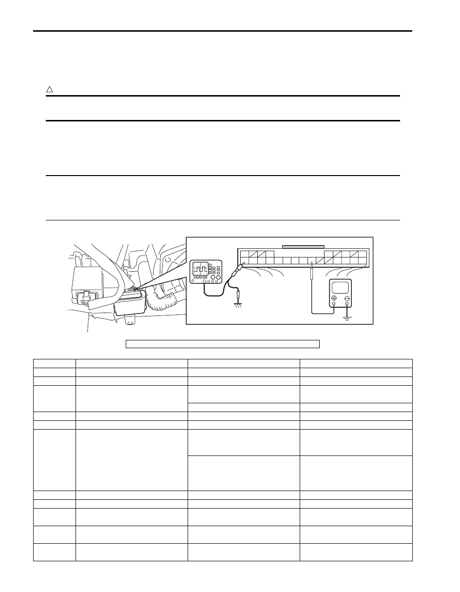
Headlight auto leveling control module and its circuits can be checked at headlight auto leveling control module wiring 
couplers by measuring voltage and pulse signal.

CAUTION

!


Headlight auto leveling control module cannot be checked by itself. It is strictly prohibited to connect 
voltmeter or ohmmeter to headlight auto leveling control module with couplers disconnected from it.


Voltage Check
Check voltage between each terminal of headlight auto leveling control module and vehicle body ground under each 
condition. If measured voltage is out of standard value, check circuit (including switch and sensor) of terminal where 
voltage was measured.

NOTE

• As each terminal voltage is affected by the battery voltage, confirm that it is 11 V or more when 

ignition switch is ON.

• Voltage with asterisk (*) cannot be measured by voltmeter because it is pulse signal.Check it with 

oscilloscope if necessary.


V

10

11

12

13

16

17

18

19

20

3

1

5

6

9

21

22

23

24

[A]

I5JB0A920014-02

[A]: Headlight leveling control module connector (viewed from harness side)

Terminal

Circuit

Specification

Condition

1

Power source

10 – 14 V

Ignition switch is at ON position.

2

3

Lighting switch

Less than 1.5 V

Lighting switch is at “HEAD” 

position.

10 – 14 V

Lighting switch is at OFF position.

4

5

6

Headlight auto leveling indicator

Continuity

For about 3 seconds after ignition 
switch is turned on (i.e., headlight 

auto leveling indicator is lit up).

No continuity

More than about 3 seconds after 

ignition switch is turned on (i.e., 

headlight auto leveling indicator is 

not lit up).

7

8

9

Ground for headlight auto leveling 
control unit

0 V

Ignition switch is at ON position.

10

Power supply for right headlight 
leveling actuator

10 – 14 V

Ignition switch is at ON position.

11

Power supply for left headlight 
leveling actuator

10 – 14 V

Ignition switch is at ON position.

Lighting Systems:  9B-16

Reference waveform No.1
Vehicle speed signal (1).
Vehicle speed signal is pulse. Pulse frequency varies depending on vehicle speed.

12

Power supply for rear height 
sensor

About 5 V

Ignition switch is at ON position.

13

Power supply for front height 
sensor

About 5 V

Ignition switch is at ON position.

14

15

16

Vehicle speed signal

Refer to “Reference waveform No.1: ”.

17

Signal for right headlight leveling 
actuator

Less than 1 V

Lighting switch is at OFF position.

1.0 – 12.6 V

For 10 seconds after turning 

lighting switch to ON position.

18

Signal for left headlight leveling 
actuator

Less than 1 V

Lighting switch is at OFF position.

1.0 – 12.6 V

For 10 seconds after turning 

lighting switch to ON position.

19

Input signal for rear height sensor

About 2.5 V

Ignition switch is at ON position.

20

Input signal for front height sensor

About 2.5 V

Ignition switch is at ON position.

21

Ground for rear height sensor

0 V

Ignition switch is at ON position.

22

Ground for front height sensor

0 V

Ignition switch is at ON position.

23

Ground for right headlight leveling 
actuator

0 V

Ignition switch is at ON position.

24

Ground for left headlight leveling 
actuator

0 V

Ignition switch is at ON position.

Terminal

Circuit

Specification

Condition

Measurement terminal

CH 1: “G51-16” to “G51-9”

Oscilloscope setting

CH 1: 200 mV
TIME: 40.0 ms/DIV

Measurement condition

Engine is running and vehicle speed 10 km/h (6 mph)

I5JB0A920037-01

9B-17 Lighting Systems: 

Repair Instructions

Headlight Housing Removal and Installation

S5JB0A9206001

WARNING

!


Be sure to read “Precautions for Discharge 
Headlight Service (If Equipped)” 
before 
starting to service work.
Neglecting them may result in personal 
injury.


Removal

1) Disconnect negative (–) cable at battery.
2) Remove front bumper. Refer to “Front Bumper 

Components in Section 9K”.

3) Remove headlight mounting bolts.
4) Detach headlight housing (1) from vehicle.
5) Disconnect couplers from headlight housing (1).

Installation
Reverse removal procedure noting the following.
• After installation, be sure to inspect and adjust aiming 

referring to “Headlight Aiming Adjustment with 
Screen”.

Headlight Bulb Replacement

S5JB0A9206002

WARNING

!


• To avoid danger of being burned, don’t 

touch when the bulb is hot.

• Don’t touch glass surface of bulb, to avoid 

deteriorate as the case may be unclear 
when bulb light on at dirty condition.

• Be sure to read “Precautions for Discharge 

Headlight Service (If Equipped)” before 
starting to service work.


Discharge headlight Bulb

1) Check to ensure that lighting switch is at OFF 

position.

2) Disconnect negative (–) cable at battery.
3) Remove headlight housing referring to “Headlight 

Housing Removal and Installation”.

4)  Remove cover (1) from headlight housing by turning 

it counterclockwise.

5) Remove igniter (2) from discharge headlight bulb by 

turning it counterclockwise.

6) Replace bulb (1) from headlight housing.

7) Install igniter (2) to discharge headlight bulb by 

turning it clockwise.

8) Install cover to headlight housing by turning it 

clockwise.

9) Install headlight housing to vehicle body referring to 

“Headlight Housing Removal and Installation”.

10) Connect negative (–) cable at battery.

11) After installation, be sure to inspect and adjust 

aiming referring to “Headlight Aiming Adjustment 
with Screen”.

1

I5JB0A920015-01

1

2

I5JB0A920016-01

1

iii)

ii)

ii)

i)

i)

I5JB0A920017-01

Lighting Systems:  9B-18

Other Than Discharge Headlight Bulb

1) Disconnect negative cable at battery.
2) Disconnect headlight coupler.
3) Remove socket cover (if equipped).
4) Remove headlight bulb (1) as shown.
5) Install new headlight bulb and assemble all removed 

parts.

Ballast Removal and Installation

S5JB0A9206023

WARNING

!


Be sure to read “Precautions for Discharge 
Headlight Service (If Equipped)” c
arefully 
before working. Neglecting them may result 
in personal injury.


Removal

1) Check to ensure that lighting switch is at OFF 

position.

2) Disconnect negative (–) cable at battery.
3) Remove headlight housing referring to “Headlight 

Housing Removal and Installation”.

4) Remove ballast (1) from headlight housing (2).
5) Disconnect connector (3) from ballast.

Installation
Reverse removal procedure noting the following.
• Connect connectors securely.
• After installation, be sure to inspect and adjust aiming 

referring to “Headlight Aiming Adjustment with 
Screen”.

[A]: Low beam bulb of headlight in which low and high beam bulbs are 

separated (bulb lock type)

[B]: Low beam bulb of headlight in which low and high beam bulbs are 

separated (socket lock type)

[C]: High beam bulb of headlight in which low and high beam bulbs are 

separated

[D]: Bulb in which low and high beams are integrated

2. Headlight bulb socket

iii)

ii)

i)

1

iii)

ii)

i)

1

ii)

i)

[A]

[B]

[C]

[D]

ii)

i)

iii)

ii)

1

2

1

2

iv)

i)

iv)

iii)

I5JB0D920017-01

1

2

3

I5JB0A920019-01


Content   ..  367  368  369  370   ..